|
|
|
|
|
|
| |
 |
| |
 |
|
|
|
|
 |
|
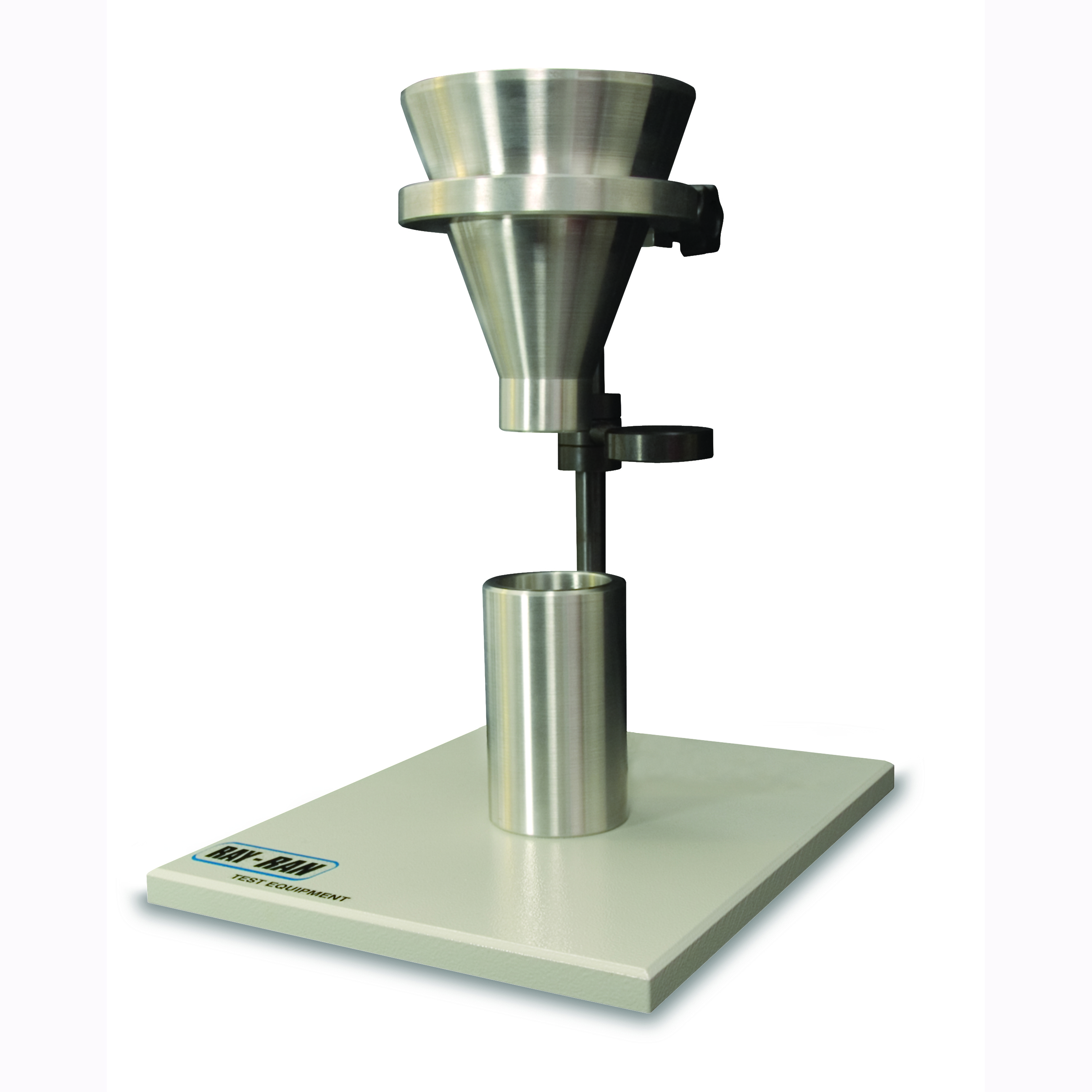
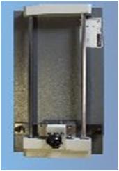
| ���� Ray-Ran���� Bulk Density Measurement System�� �Ŀ�� �� Pellet, Coarse, Cut Fibers ���� Apparent Density, Bulk Factor ���� ������ �� �ִ� �е����Դϴ�. ����ũ� ���� ASTM D 1895�� ������ 3���� ���� ����� ä���ϰ� �ֽ��ϴ�. |
|
|
 |
Apparent Bulk Density
Product Description
Apparent Bulk Density. Ray-Ran offer 4 models which are used are used to measure apparent density, bulk factor, and where applicable, the pourability of plastic materials in forms such as moulding powders. There are three methods according to the ASTM D 1895 standard and one to the ISO R60 standard that are applicable to various forms of these materials that are commonly encountered - from powders and granules to large flakes and cut fibers.
The Apparent Bulk Density measurement provides a very good indication of the handling, packing and the space requirements. The pourability parameters indicate of how well the material will flow through feed tubes and hoppers. |
|
|
|
Standard features include
Funnel (made from solid aluminium), stand, measuring cup (made from solid aluminium), shut off disk, Product user manual, traceable certificate of calibration, CE mark of conformity |
|
|
|
Test Description
Apparent Bulk Density- The material is freely poured through a funnel into a measuring cup of a known volume. By weighing the measuring cup empty and full, the Apparent Bulk Density is found. |
|
|
|
Part Numbers
RR/BDA/D1895A ASTM D1895 method A, RR/BDA/D1895B ASTM D1895 method B, RR/BDA/D1895C ASTM D1895 method C, RR/BDA R60 ISO R60 |
|
|
|
Complies with Standard(s)
ISO 60, BS 2782 Method 621A, ASTM D1895 |
|
|
|
|
| |
|
|
|
| |
|
|
 |
| |
|
|
|
| |
 |
|
|
|
|
 |
|
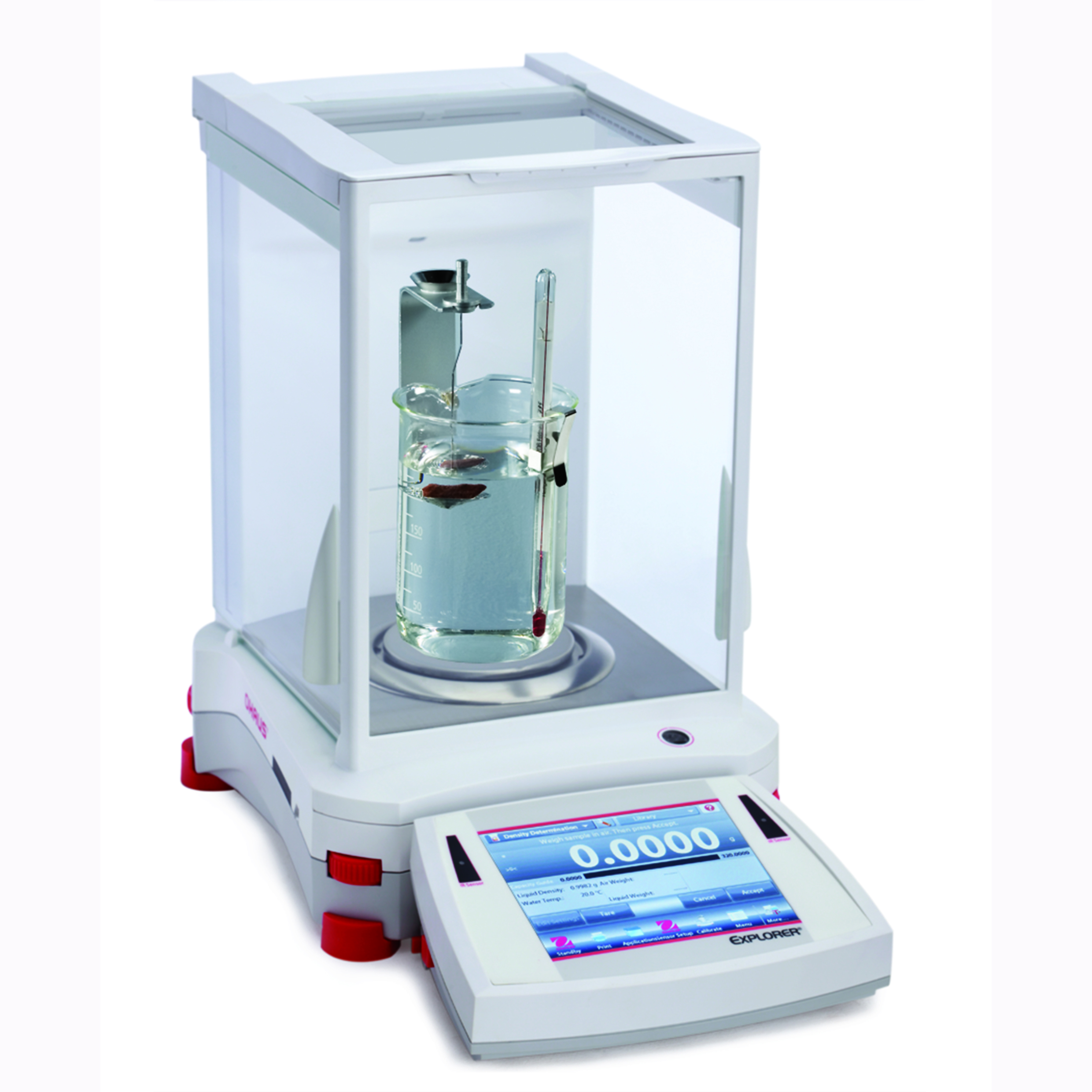
| Archimedean Buoyancy ������ �̿��� Density Balances (�е���)�� ��ü�� �е��� ��ü�� ������ ��� ������ �� �ֽ��ϴ�. 0.1mg ���� ���� ������ �����մϴ�. |
|
|
|
Product Description
All purpose analytical balance, for parts counting, check weighing etc and which can easily be converted to a Density balance with the addition of the Density Determination Kit.
The balance has built in software that will automatically calculate both solid & water densities, with a density table for water at temperatures at 10oC to 30oC built in. As well as the normal weighting functions like statistics, formulation etc.
62g, 110g, 210g, 410g, or 610g capacity versions available, Dual Range model 100 / 210g also available. - Readability 0.1 mg or 1.0mg (0.1 / 1.0 mg on dual version). |
|
|
|
Standard features include
Funnel (made from solid aluminium), stand, measuring cup (made from solid aluminium), shut off disk, Product user manual, traceable certificate of calibration, CE mark of conformity |
|
|
|
Test Description
The test sample is first weighed in air and again when submerged in a liquid. By determining the loss in weight which is directly proportional to the mass of the fluid it has displaced, the specific gravity and density is readily calculated using the built in software |
|
|
|
Part Numbers
RR/VOG64 (64g Capacity), RR/VOG413 (410g Capacity), RR/VOG214DM (100g/210g Dual capacity) |
|
|
|
Complies with Standard(s)
ASTM D792, ASTM D1622, ISO 1183 |
|
|
|
| |
|
|
|
| |
|
|
|
| |
|
|
|
| |
 |
|
|
|
|
 |
|
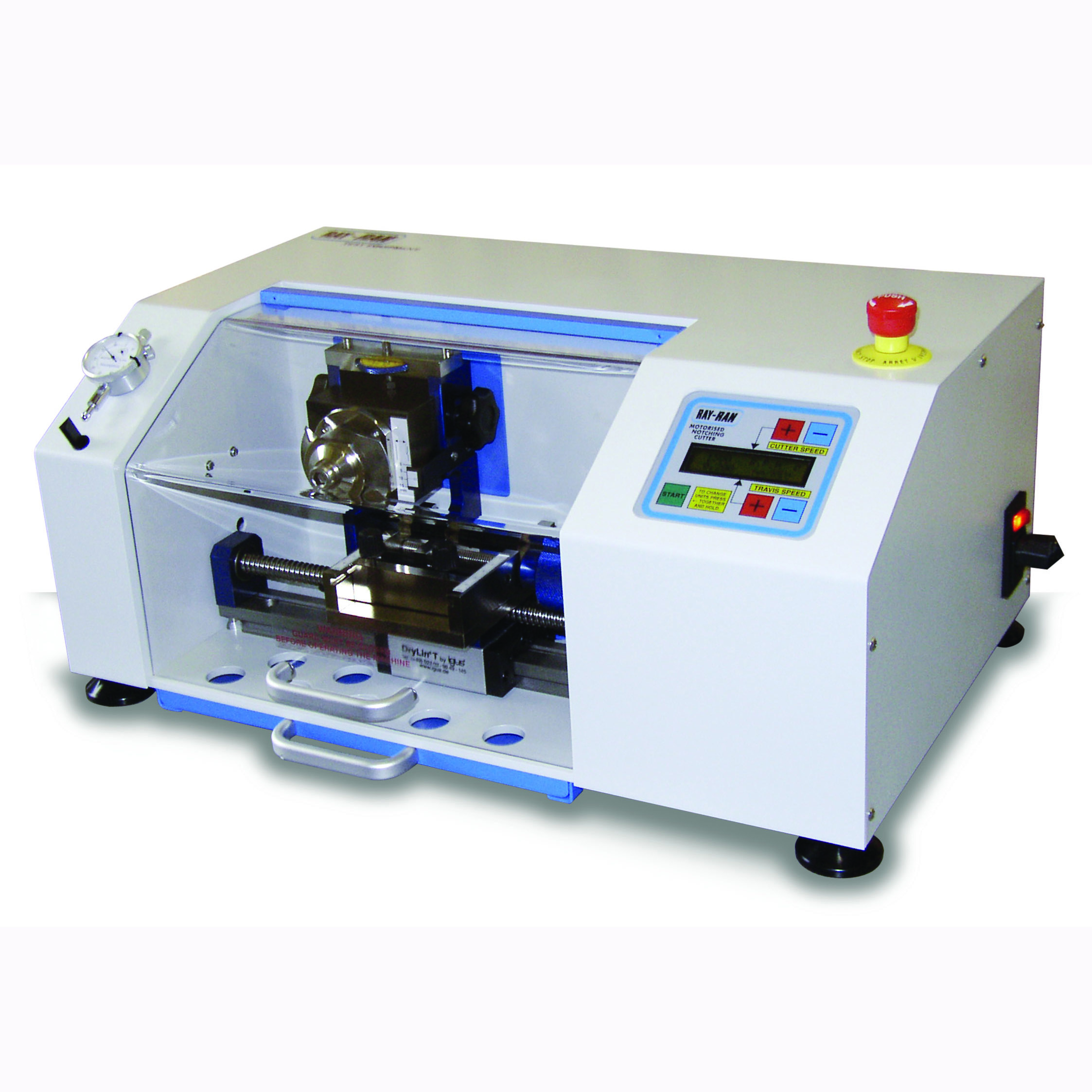
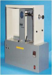
| �����ϰ� ������ 2���� Į���� ����Ͽ� �ö�ƽ �� �پ��� ������ ��Ḧ ���Ͻô� ������� �����ϰ� ������ �� �ֽ��ϴ�. ��ü�������� ����� LCD ȭ������ ������ ���� �����մϴ�. |
|
|
|
Product Description
The Auto Cycle Notching Cutter. has been designed to machine a very precise stress concentration notch in test specimens to ensure that breakage of the specimen takes place at the same section each time a test is carried out. Mainly intended for use with plastic polymer materials, the variable speed range of the cutter and traverse feed enables the optimum cutting conditions to be established for each different material
The apparatus is capable of producing notch profiles to all International test standards, such as ASTM D256, ISO 179 and 180. The cutters are made from tungsten carbide which is an extremely hard and durable material. The cutting edges are optically profile ground to very close tolerances. Different cutter profiles are available to suit standard and special notch requirements.
The Dual Tooth Cutting Wheels are made from tungsten carbide with cutting edges that optically ground to very close tolerances. The standard wheel fitted to the apparatus is the 0.25mm radius cutter. However 0.1mm and 1.0mm radius, and 0.8mm and 2.00mm �U?notch cutter wheels are available. Ray-Ran is also able to offer wheels to customers specifications if required. |
|
|
|
Standard features include
Advanced dedicated microprocessor control, Optical profile ground and diamond lapped dual tooth cutter wheels, Notches to any International test standard including Izod, Charpy, "U" and "V" notches, Notch depth dial indicator comparator, Slip gauge to set up the dial indicator comparator to accurately measure the remaining width under the notch, Micro adjustment notch depth, Standard notch depth setting blocks
Multi-sample loading, Setting rail forming an integral part of the vice to centralise test samples, Variable cutter speed with memory feature, Cutter speed range from 350 rpm to 2000 rpm, Anti-vibration linear motion slide, Variable metric and imperial traverse speeds with memory feature, Traverse speed range from 0.081 mm/rev to 1.0 mm/rev (0.003 in/rev to 0.04 in/rev), Fast return traverse speed, Easy to read digital speed liquid crystal display, Touch membrane keypad, Easy clean removable waste tray, Fully traceable certificate of calibration, Product user manual, CE mark of conformity, 1 year return to base warranty. |
|
|
|
Test Description
Adjusted the settings for the notch depth and central position. Notch a test sample and measure notch depth. If necessary, make any fine adjustments. Multiple samples can now be notched. |
|
|
|
Part Numbers
RR/NC - Auto Cycle Test Sample Notching Cutter. NC 051A - 0.100mm Radius Cutter. NC 051B - 0.250mm Radius Cutter. NC 051C - 1.000mm Radius Cutter. NC 051D - 0.800mm "V" Notch Cutter. NC 051E - 2.000mm "V" Notch Cutter. |
|
|
|
Complies with Standard(s)
ISO 180, ISO 179, ASTM D256 |
|
|
|
| |
|
|
|
| |
|
|
|
| |
|
|
|
| |
 |
|
|
|
|
 |
|
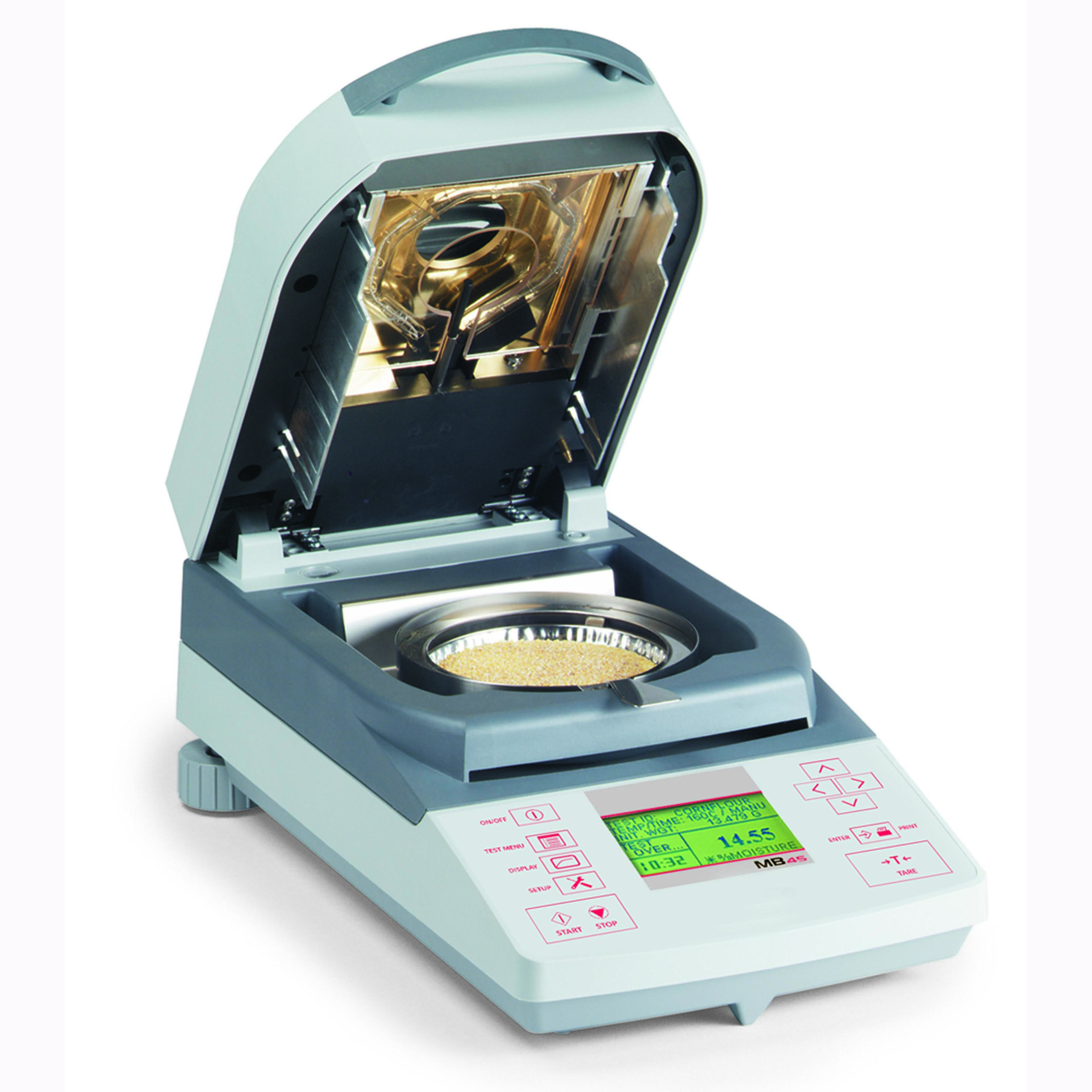
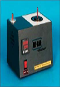
| ���� ���� ���е��� 1.0mg���� ������ ������ �����ϴ� ���Ա��� ���� �����ϰ� �ִ� 50���� ������ ������ �� �ֽ��ϴ�. ��� �µ� ������ 50~200���Դϴ�. |
|
|
|
Product Description
The Ray-Ran MB series of Moisture Analysers are a thermogravimetric apparatus based on the halogen radiator technology. This instrument can be used to measure the moisture content is a wide variety of materials.
The MB45 is equipped with a halogen radiator which is more responsive to the heating & cooling requirements than traditional IR heaters. To ensure even heat distribution, a gold plated reflective shield lines the inside lid of the analyser. This gold plating is specifically used for its reflective properties and the ability to dissipate heat. A highly sensitive precision balance is built into the apparatus to allow for the detection of weight changes of 0.001 grams and 0.01% moisture loss. |
|
|
|
Information Displayed
% moisture, % solids, time, temperature, weight, test ID drying curve. |
|
|
|
Standard features include
45g Capacity - Readability 0.01% / 0.001g - 50o to 200o C Temperature range in 1o increments - Built in timer 1 to 120 minutes in 10 second increments - Storage of 50 drying programs - Backlit graphical display with real time drying curve - Built in RS232 interface to connect to PC or Mini Printer - Pan handler included - Built in language support (English, Spanish, German, French & Italian) - Fully traceable certificate of calibration |
|
|
|
Test Description
The sample material is weighed at the start of the test and again after the heating cycle is finished. The loss in weight equates to the moisture content that has been evaporated. |
|
|
|
Part Numbers
RR/MB45, RR/MB35 |
|
|
|
| |
|
|
|
| |
|
|
|
| |
|
|
|
| |
 |
|
|
|
|
 |
|
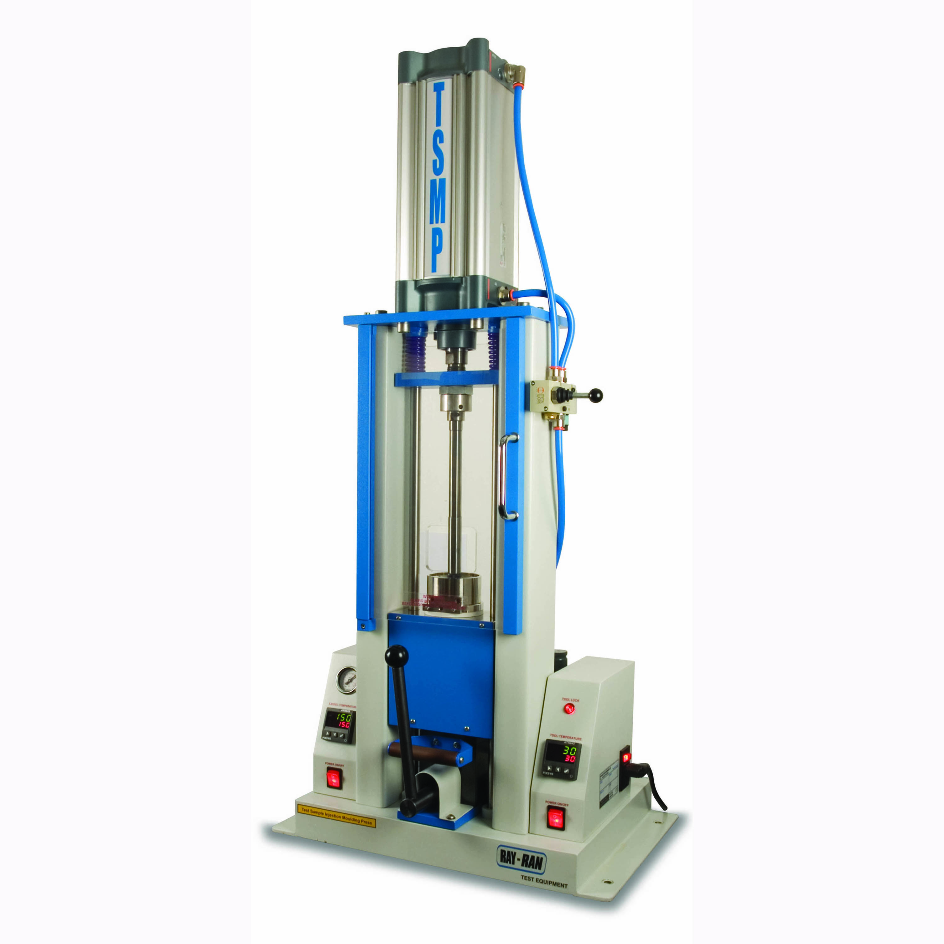
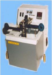
| �Ŀ���� �縴Ÿ�� �Ը��� �������� �÷Ḧ ����Ͽ� ������ �����ϴ� ����Դϴ�. ������ ����� �µ� ���� ��ġ�� ����ϰ� ��������� �����ݴ��� �������� ���Դϴ�. |
|
|
|
Product Description
The Ray-Ran Test Sample Injection Moulding Machine is a low cost sample moulding machine with a compact design for vertical bench mounting. The simple Cylinder/Die extraction system eliminates purging when changing from one colour or material to another.
The machine is supplied with a basic cam-operated tool block with Special bearings to accommodate the Increased Pressure which will accept any number of low cost tool inserts machined to any shape that will fit within the Tool Block parameters of 175mm x 40mm x 12.7mm.
Tool Inserts to suit any International Standard, e.g. ASTM, ISO, DIN, JIS, etc., can be supplied for tensile dumbbells, colour plaques, impact bars, etc.
The apparatus has been designed to operate up to 10 bar (150 psi) which is adequate for moulding most materials. Digital heating up to 400 deg C melts the polymer which is the extruded into the mould. Digital tool block heating is included for more efficient polymer flow into the mould with temperatures up to 200 deg C to prevent freezing. |
|
|
|
Standard features include
Quick release cam-lock tool block, Digital temperature controlled cylinder, Automatic Nozzle-to-tool Locking Device. A Unique Design that intensifies the Locking Force as the Injection Pressure increases, Polymer feeder Hopper, Small footprint for Bench Mounting, Low cost Tool Inserts to all International Standards, Quick Change Cylinder, Nozzle and Die, Audible and Visual alarms for Tool Locking, |
|
|
|
Optional accessories available
Interchangeable cylinders to 70cm3, Interchangable Nozzles & Die�s, Compressor. |
|
|
|
Test Description
Test Sample Injection Moulding Apparatus.
Will accept very small quantities of polymer in granule, powder or similar form. |
|
|
|
Part Numbers
RR/TSMP 2 - Model 2 Test Sample Moulding Apparatus. TSMP A030 - Basic Tool Block. TSMP 060 - Digital Heating Package. TSMP 022 - Spare Quick Change Cylinder + Lock Nut. TSMP 024 - Cylinder Nozzle. |
|
|
|
| |
|
|
|
| |
|
|
|
| |
|
|
|
| |
 |
|
|
|
|
 |
|
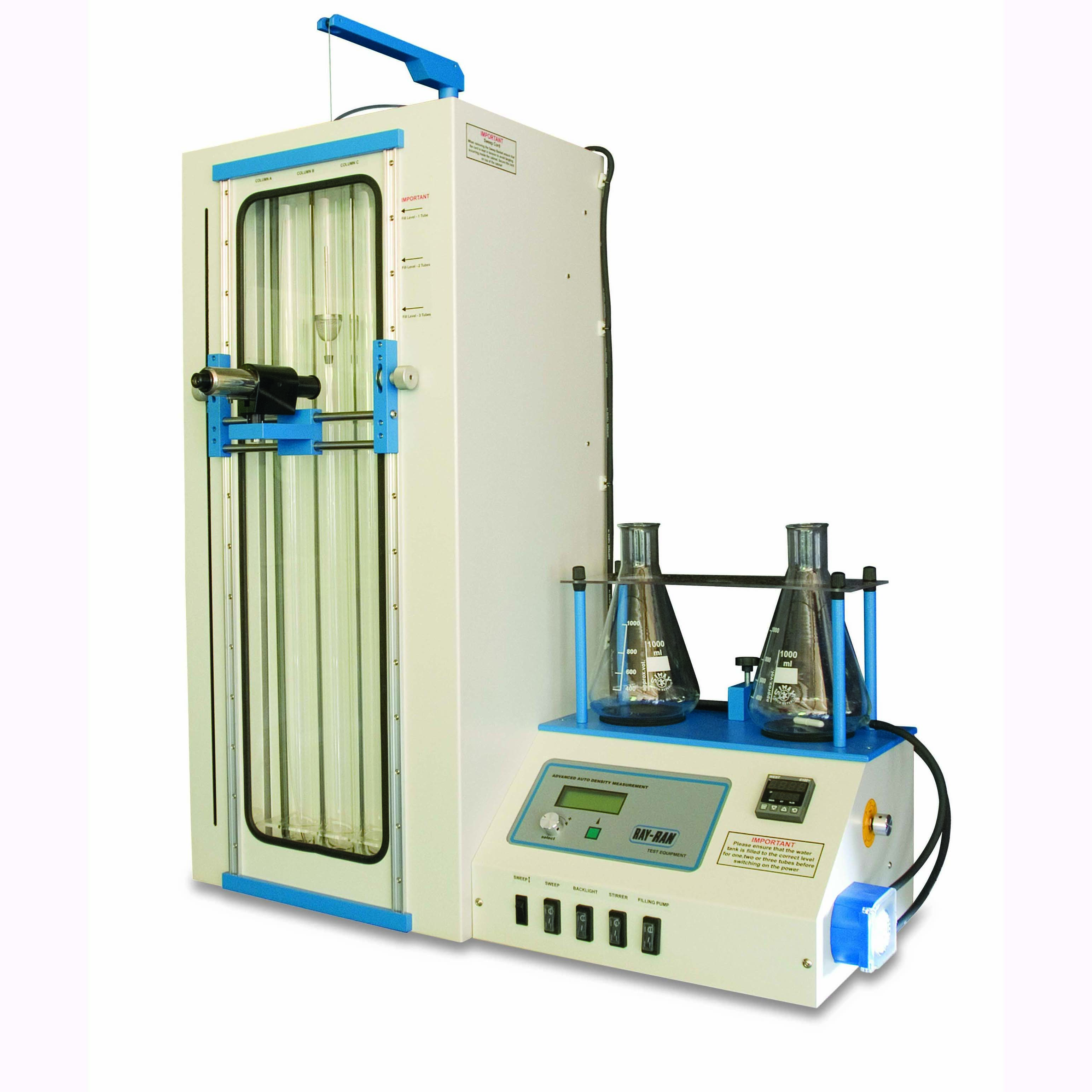
| ASTM D1505 & ISO 1183 Method D �� ���� small solid materials, in various forms, Pellets, Granules, film ���� �е��� �����մϴ�. |
|
|
|
Product Description
Digital Readout Density Column. - The gradient column method accurately measures the density of small solid materials, in various forms, Pellets, Granules, film etc..and conforms to the ASTM D1505 & ISO 1183 Method D standards.
The density is formed by mixing two fluids having different densities. The resulting solution has a density which when introduced into the column increases uniformly from top to bottom.
Ray-Ran's new advancement means that density measurements can be made more quickly and more accurately.
The height of the calibrated marker floats or samples introduced into the density gradient are measured using a trammel guided "sight" connected to a positional encoder relaying the height position to a microprocessor so that the density can be obtained without the need for graphs etc.
This also means that the Gradient can be calibrated & checked at any time. |
|
|
|
Standard features include
Microprocessor System to accurately calculate the Density of the Sample. Twin conical flask pumped filling apparatus with motorised magnetic stirrer, Automatic column clearing device - sweep basket arrested automatically at top and bottom of column and pivoted for use over any of the 3 columns, Digital Temperature Controller accurate to +/- 0.1 �C, RS232 output, Built-in cooling coil, black or white twin background to assist sighting different colour samples, Microprocessor Auto Calibration System, Fully traceable certificate of calibration, Product user manual, CE mark of conformity |
|
|
|
Optional accessories available.
Microprocessor Controlled Filling System, Water chiller unit, glass marker floats, Thermal printer |
|
|
|
Test Description
When a sample material is placed in the density column its height in the column is measured using the trammel system "sight" and the microprocessor then calculates the corresponding density. |
|
|
|
|
|
Part Numbers
RR/DGA .- Auto Density Measurement System .- RR/DGA/CFS. - Computerised Filling System - RR/DGA/CU. - Water Chiller Unit - DGA/FLOAT/001. - Glass Marker Floats (density from 0.8 g/ml to 1.599 g/ml)DGA/FLOAT/002. - Glass Marker Floats (density from 1.600 g/ml to 2.200 g/ml)DGA/FLOAT/003. - Glass Marker Floats (density from 0.7 g/ml to 0.799 g/ml) |
|
|
|
Complies with Standard(s)
ISO 1183, ASTM D1505 |
|
|
|
| |
|
|
|
| |
|
|
|
| |
|
|
|
| |
 |
|
|
|
|
 |
|
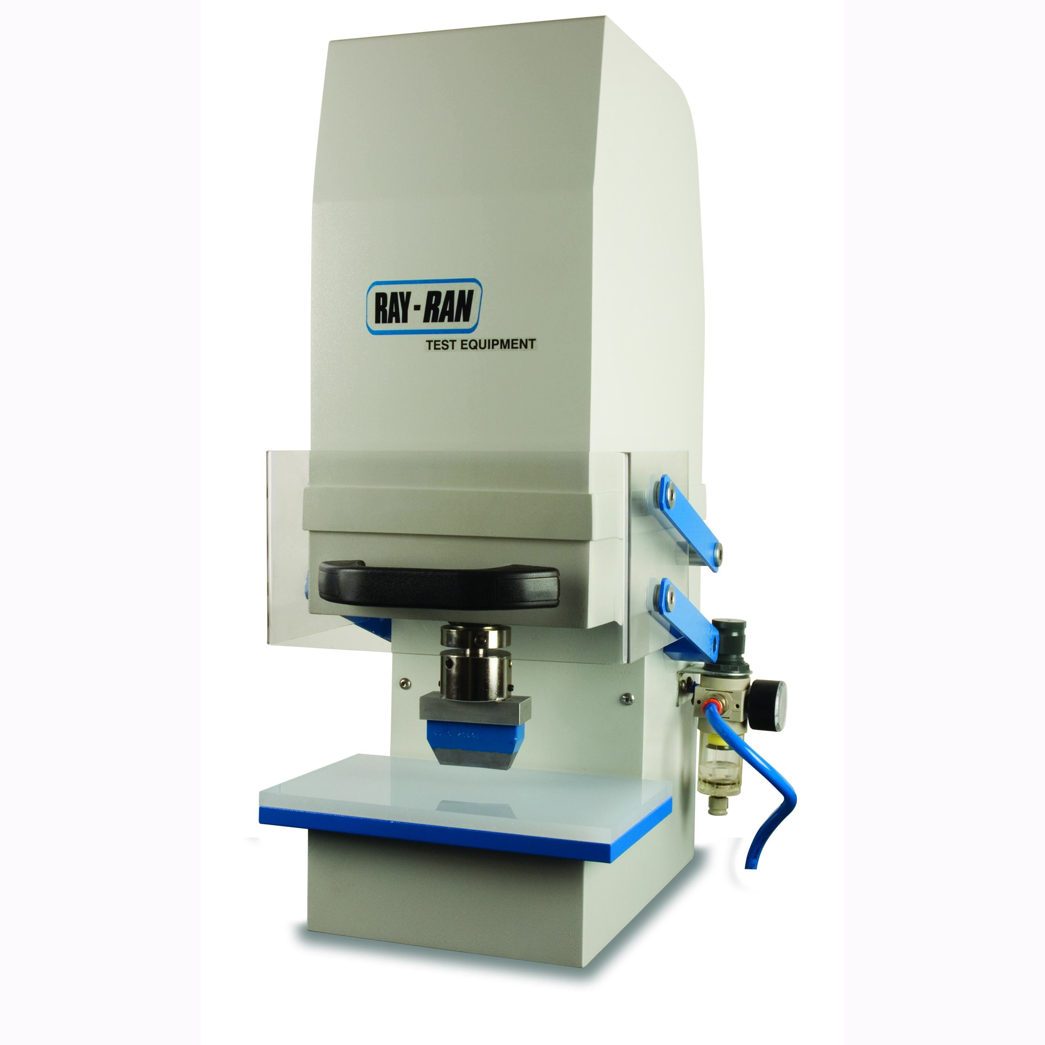
| Pneumatically Operated Cutting Press�� �ִ� 5,000kg�� ���� ���� ��ų �� �ֽ��ϴ�. Ŀ�� ������ ������ �о� �ö�ƽ, ����, ����, ���� �� �پ��� ���ÿ� ���� Ŀ�� �����Ͽ� ���� �����մϴ�. |
|
|
|
Product Description
The Pneumatically Operated Test Sample Cutting Press has been specifically designed to cut shapes such as test samples from relatively flexible materials, such as plastics, fabrics, boards and paper. In most cases, the thickness of the material that can be cut will not just depend on the strength of the material, but also on the lateral flexibility of the material to allow the cutter to penetrate down into, and pass through the material. In other words, if the material is too rigid, the thickness of the material that can be cut will be reduced because the outside edges of the cutter blades will bind in the material, and therefore reduce the available cutting force. The press generates on average up to 5000kg (50KN) of cutting force. The press has been designed to operate up to 10 bar (150 psi) but generally 7 bar (100 psi) will be adequate for cutting most materials. |
|
|
|
Standard features include
Pneumatically operated, Polycarbonate safety guard, 0?0 bar pressure regulator, Fine height adjustment of cutter, Supplied with cutting mat, Arbour locking tool, Hexagon key, 1 year return to base warranty, Product user manual. |
|
|
|
Optional accessories available
Cutting tools to any shape or standard, Different shanks to suit most cutting presses, larger bed & throat sizes can be manufactured, Compressor.
Ray-Ran also produce a wide range of cutters for this Press - see separate heading Cutters |
|
|
|
Test Description
Pneumatically Operated Cutting Press |
|
|
|
Part Numbers
RR/PCP Pneumatic Cutting Press, PCP/XBG 039 Spare Cutting Mat |
|
|
|
| |
|
|
|
| |
|
|
|
| |
|
|
|
| |
 |
|
|
|
|
 |
|
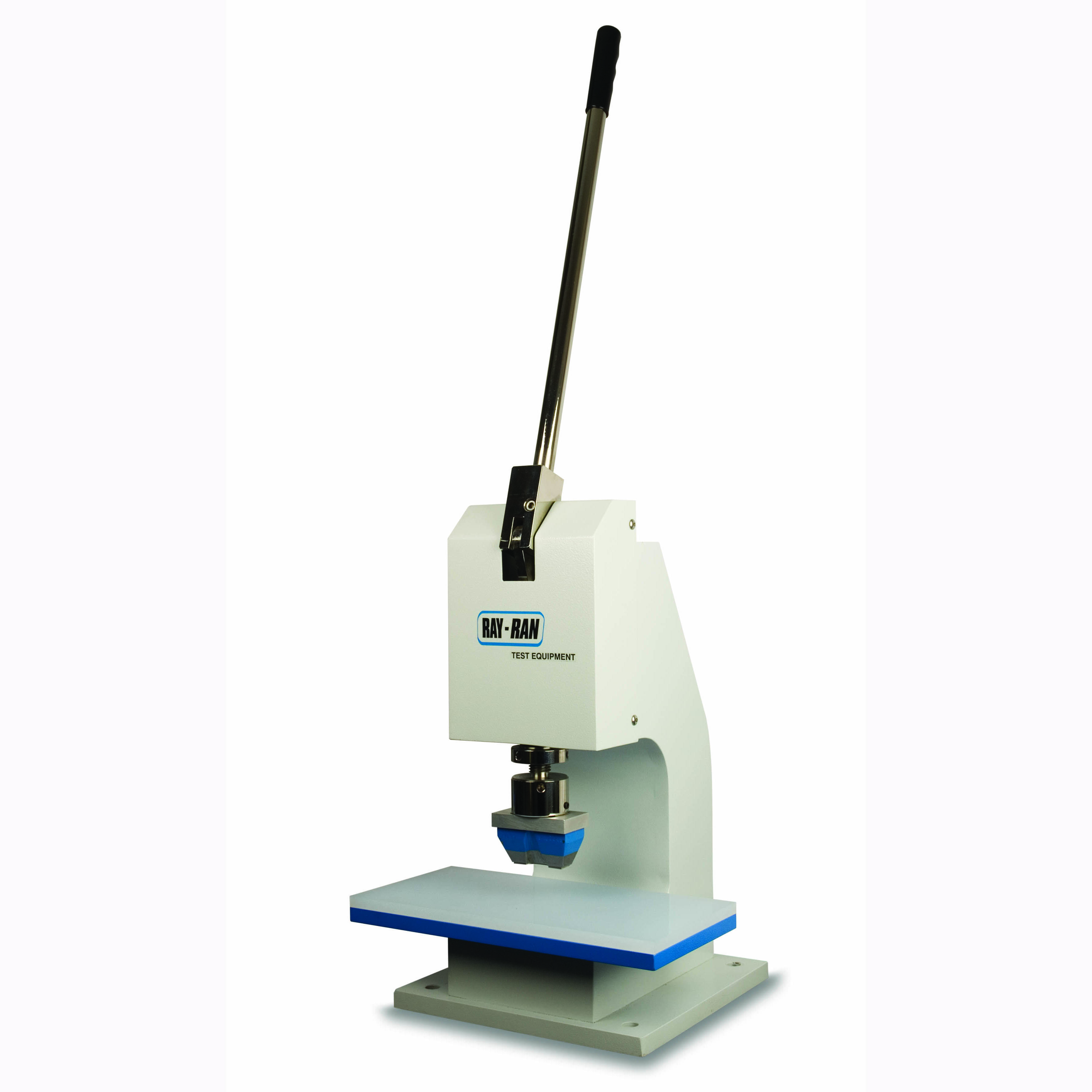
| �������� �����ϴ� Cutting Press�� �ִ� 600kg�� ���� ���� ��ų �� �ֽ��ϴ�. Ŀ�� ������ ������ �о� �ö�ƽ, ����, ����, ���� �� �پ��� ���ÿ� ���� Ŀ�� �����Ͽ� ���� �����մϴ�. |
|
|
|
Product Description
Hand Operated Cutting Press. - The Hand Operated Test Sample Cutting Press has been specifically designed to cut shapes such as test samples from relatively flexible materials, such as plastics, fabrics, boards and paper. In most cases, the thickness of the material that can be cut will not just depend on the strength of the material, but also on the lateral flexibility of the material to allow the cutter to penetrate down into, and pass through the material. In other words, if the material is too rigid, the thickness of the material that can be cut will be reduced because the outside edges of the cutter blades will bind in the material, and therefore reduce the available cutting force. The press generates on average up to 600kg (6KN) of cutting force. (Dependant on strength of operator). |
|
|
|
Standard features include
Fine height adjustment of cutter, Supplied with cutting mat, Arbour locking tool, Hexagon key, 1 year return to base warranty, Product user manual. |
|
|
|
Optional accessories available
Cutting tools to any shape or standard, Different shanks to suit most cutting presses, Cutting Mats,
Ray-Ran also produce a wide range of cutters for this Press - see seperate heading called Cutters |
|
|
|
Test Description
Hand Operated Cutting Press. |
|
|
|
Part Numbers
RR/HCP - Hand Cutting Press, NCP/XBG 038 Spare Cutting Mat |
|
|
|
| |
|
|
|
| |
|
|
|
| |
|
|
|
| |
 |
|
|
|
|
 |
|
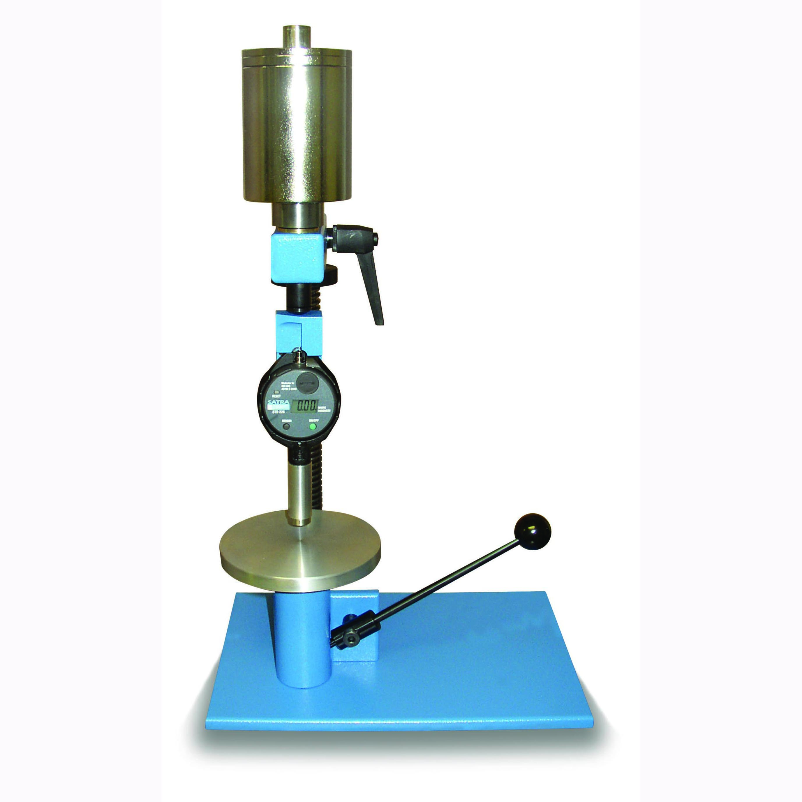
| ������ ����� ����Ͽ� �����ϰ� ��Ȯ�մϴ�. �ִ� 75mm �β��� ���� ����, �پ��� ����(0.27kg,1kg,5kg)���� �ݺ� �������� �ִ� ���� �浵�� ������ �� �ֽ��ϴ�. �ְ� 7���� ������ ���� �� �м�, ����� �����մϴ�. |
|
|
|
Product Description
Durometers measure the penetration depth (into the sample material) of an indentor reacting against a calibrated spring load, and the result is given in Shore hardness degrees, displayed either on an analogue scale or as a digital readout. Durotech MDS Durometers separate the displacement measurement and display element from a module containing the indentor and spring. Additional modules can be purchased at any time if the scope of the material hardness alters. Each module is individually calibrated, its calibration status being unaffected by the host Durometers.
Hardness values range from 0 (full penetration) to 100 (no penetration), Full penetration is between 2.46mm and 2.54mm (0.097 and 0.100 in) depending upon the equipment used. It is recommended that shore D is used when Shore A results are greater than 90 and shore A is used when shore D results are less than 20.
The pocket MDS Universal Durometer is a robust instrument incorporating a precision analogue movement or digital display. It is traditionally styled with MDS technology, complete with tolerance hands. A maximum hand option is available and the model fits to any operating stand for improved repeatability.
The modular setup allows simple & quick changing of shore modules. |
|
|
|
Test Description
Fit the instrument with the correct module. Place and press the instrument perpendicular to the surface to be tested and read off the result. |
|
|
|
Part Numbers
D202 Digital Durometer with 1 Module, D20200 For 00 Module.B202 Analogue Durometer with 1 Module, BS550 Durometer Stand. |
|
|
|
Complies with Standard(s)
JIS K6301, JIS K6253, ISO 868, ISO 7619, ISO 48, DIN 53519, DIN 53505, ASTM D2240, ASTM D1415 |
|
|
|
| |
|
|
|
| |
|
|
|
| |
|
|
|
| |
 |
|
|
|
|
 |
|
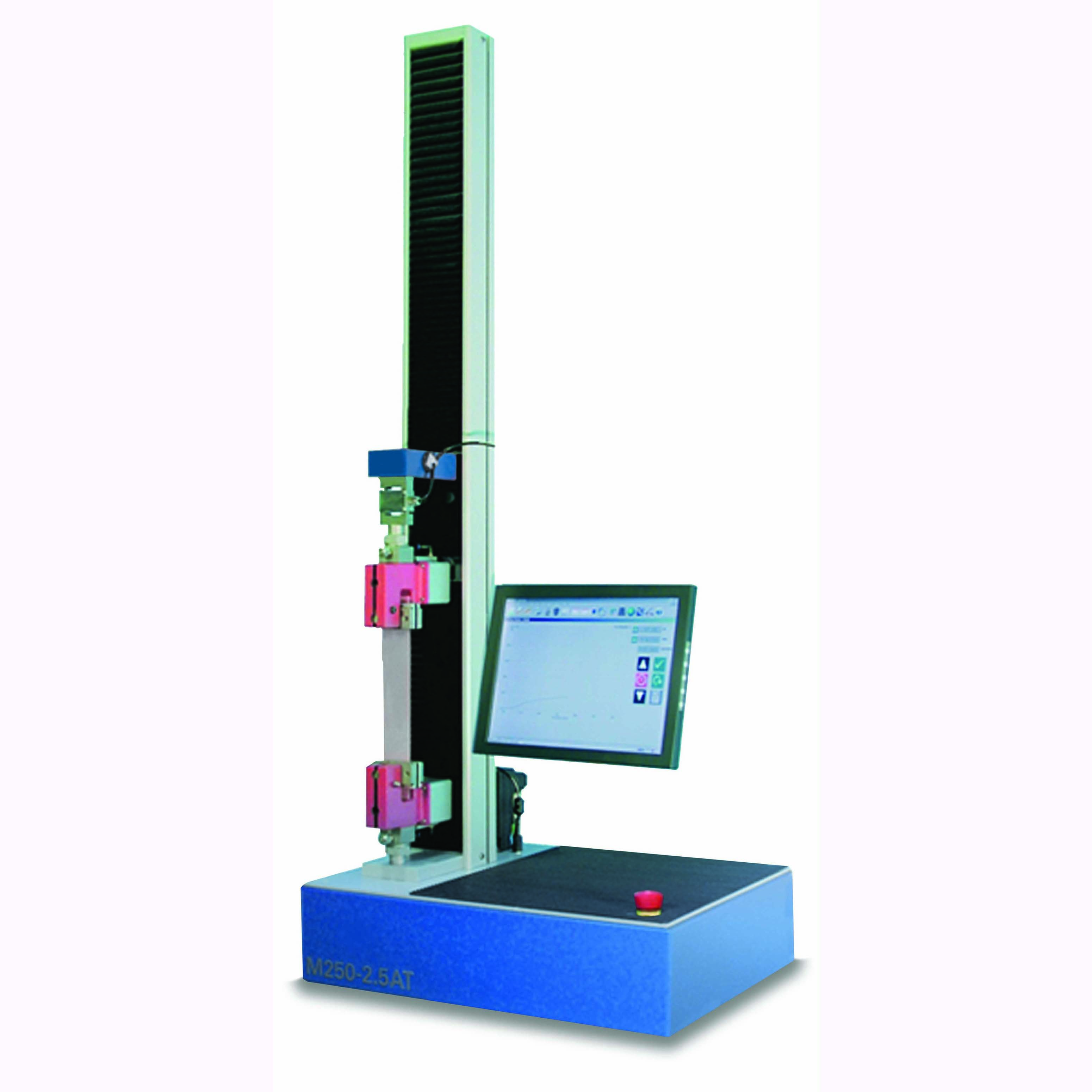
| �ִ� 300kN ���� �ε弿�� ���� ����, ���� �� ���� ��尡 �����ϸ� ���� ���е��� ���� �������� �پ�ϴ�. ���� �÷� ���÷��̰� �����Ǿ� ���� ����, ����� �����մϴ�. |
|
|
|
Product Description
A Universal Testing Machine otherwise known as a materials testing machine or test frame is used to test the tensile and compressive properties of materials. Such machines generally have two columns but single column types are also available. Load cells and extensometers measure the key parameters of force and deformation as the sample is tested. These machines are widely used and would be found in any materials testing laboratory.
A typical testing system is comprised of a materials testing machine or test frame, control and analysis software, and critically, the test fixtures, accessories, parts and devices used to hold and support the test specimen.
A comprehensive range of tests can be carried out such as Tensile, Compression, Crush, Friction, and Flexural on materials like Plastics, Metals, Paper, Fabric, Yarn etc.
The CT Series bench mounted single or twin column universal strength testing machines. A PC is required for operation & results presentation. These machines use the feature-rich winTest software running under the Windows operating system for control and testing that is compliant with all relevant industry standards. Advanced, standard and complex multistage test procedures are fully configurable and controlled using the standard PC interface. PC systems can be supplied or customers can utilise their own PC. |
|
|
|
Standard features include
High specification Computer controlled Universal testing machine, Max tension and compression resolution 0.1N, 800% overload capability on load cells, Accuracy of better than +/- 0.5% of indicated reading down to 1/1000th of load cell, Meets and exceeds BS EN ISO 7500-1 1999 Tension Grade 0.5, Compression Grade 0.5 and meets all other International standards, Force sampling rate 1000/s Rigid Dual Column Frame with Crosshead guidance system PC control of crosshead position, resolution 0.001mm, Twin recirculating ballscrews eliminating off centre loading, High accuracy closed loop speed control Test speed 0.001 to 1000 mm/min, RS232 output for PC, Fixed load and travel protection limits, User selectable load and travel limits, PC Controlled load and extension cycle testing, plus long term creep testing, Digital control specimen break detection, Automatic check and adjustment of machine calibration, Impact and overload protection, Auto zero, Direct connection to extensometers, Aluminium extruded columns with integral T slots for mounting of accessories such as extensometers, guards, lighting etc, Supply voltage 200/240V AC or 100/120V AC at 50 or 60 Hz. |
|
|
|
Optional Accesories available
400 different grips available, Wedge, Tensile, Pneumatic, spring action etc, 3 and 4 point bending fixtures, Compression Platens, Extensometers, Test Chambers. |
|
|
|
Test Description
The following procedures can be carried out - Tension, Compression, Shear and Cycling |
|
|
|
|
| |
|
|
|
| |
|
|
|
| |
|
|
|
| |
 |
|
|
|
|
 |
|
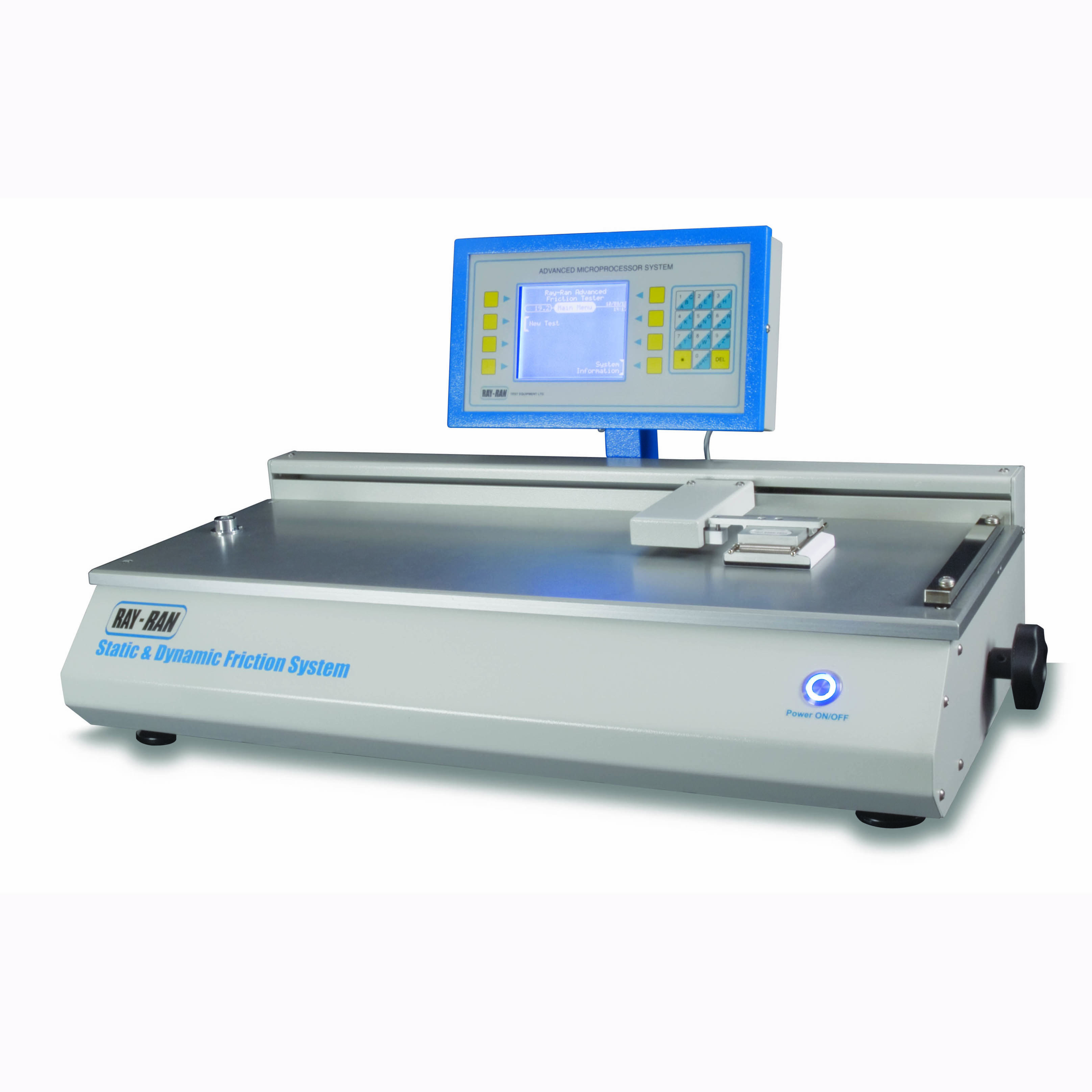
| ���ÿ� ������ �մ� ������� ����� ���� ��ݰ�������
�����ϴ� ����Դϴ�. ���ڹ������ �۵��ϴ� �ظӸ� ����Ͽ�
��ݰ��� ��Ȯ�ϰ� �����ϰ� ��� �����ϸ� ��ü��������
����� LCD ȭ������ ������ ���� �����մϴ�. |
|
|
|
Standard features include
Advanced dedicated microprocessor control, Touch membrane Alpha / Numeric keypad for data entry, LCD display for sequence logic menu auto prompt selection, Yes / no mode selector, RS232 output with data transfer lead, Specview ?Scada?software to allow PC control of Tester and real-time viewing of results, Self-calibration procedure, Results downloaded to PC for spreadsheet analysis, Metric units of measure, Ability to store User Names and Material Types, Recipe Manager to store and upload data, High resolution positional encoder, Variable pendulum velocity, Solenoid pendulum release with audible pre-warning, Levelling device, Full safety guarding electrically inhibiting operation when not closed, Fully traceable certificate of calibration, Product user manual, CE mark of conformity, 1 year return to base warranty, |
|
|
|
Optional accessories available
Guard Enclosure, Low Temperature Chambers, Tups to Customers specifications, |
|
|
|
Test Description
Puncture Impact test
In this test the principle is to determine the puncture impact resistance of thin materials, such as films and membranes. The pendulum hammer forms a puncture arm having a tup at the end point to strike the test sample. The tup profile can be designed to suit different types of failure modes. For example, a tup with a large radius end produces a high degree of elongation before rupturing the sample, where as a sharp cone profile produces a brittle type failure.
Puncture testing is a new method of determining the impact strength of materials. Although it may appear like dart drop testing, the results obtained are much more accurate and reliable because non failures are not included in the test results. Also, the tests can be used to simulate what can happen in service by using a tup that is the same profile as the component to be packaged. |
|
|
|
Part Numbers
RR/IMT - Pendulum Impact Tester IMT A100 - Puncture Stand RR/IMT/Puncture - 1.30 to 25 Joule Variable Weight Puncture Hammer. |
|
|
|
| |
|
|
|
| |
|
|
|
| |
|
|
|
| |
 |
|
|
|
|
 |
|
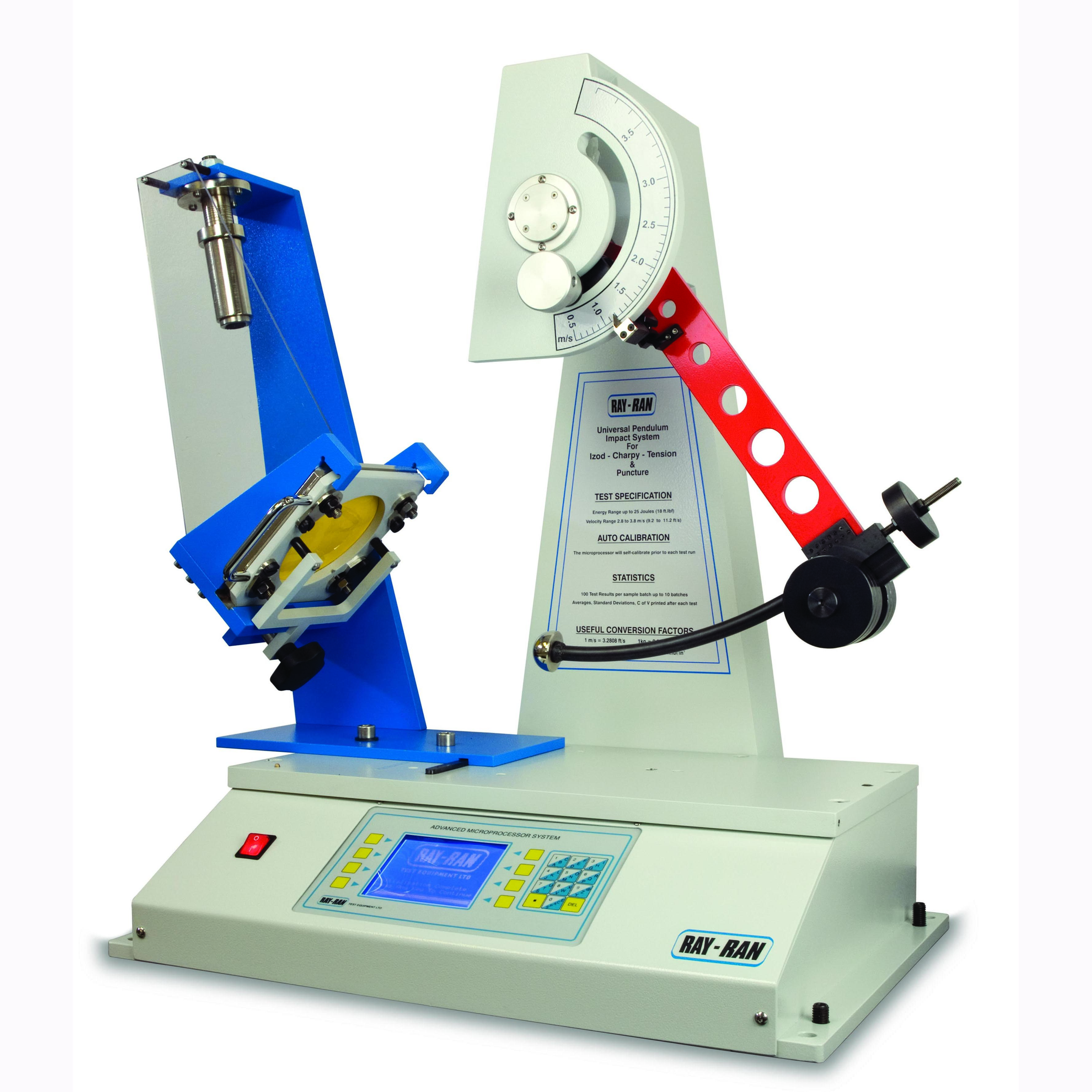
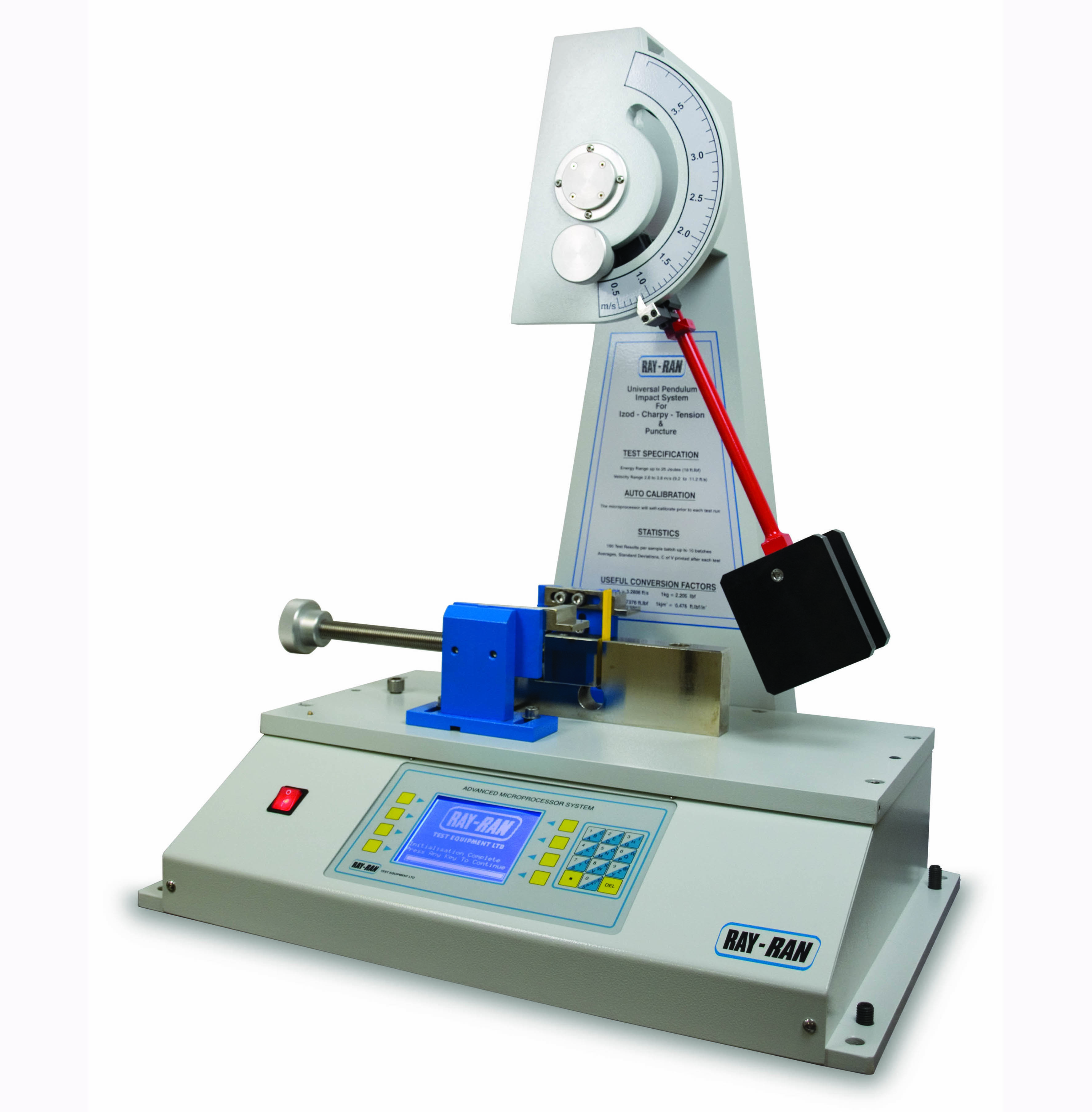
| ���ڽ� ��� �����ν� ����ǥ�ر��� ���ڹ�� �ظӸ� ����Ͽ� ��ݰ��� ��Ȯ�ϰ� �����ϰ� �����ϸ� Izod Test, Charpy Test, Tension Impact Test, Puncture Impact Test, Component Test 5������ ��������� ����ϰ� �ֽ��ϴ�. |
|
|
|
Product Description
Advanced Pendulum Impact Tester determines the energy required to break or rupture specimens of plastics or ceramics. The apparatus conforms to all of the international test standards including ASTM D256, ISO 179 and 180 for Izod, Charpy Testing , ASTM D1822 for Tension Impact Testing and other recognised standards.
The design utilises advanced dedicated microprocessor technology for simplicity, ease of operation, high accuracy and repeatability of results.
This apparatus is extremely versatile and allows impact velocities from 1.5 m/s up to 3.7 m/s combined with variable weight hammers to give an impact energy range up to 50 Joules. A special impact energy diagnostic programme has been included to assist the operator to select the correct size of Hammer for the Standard and material being tested.
The SCADA Software enables the Tester to be controlled via the PC. SCADA allows the use of recipes to upload frequently used test parameters and combine them with a operating strategy which ensure the procedures are correctly carried out. The test parameters and operating results can be displayed on screen, printed and/or archived as standard CSV files in which can be viewed or manipulated in Excel.
The apparatus also offers a Self Calibration procedure for bearing resistance and windage. |
|
|
|
Standard features include
Advanced dedicated microprocessor control, Touch membrane Alpha / Numeric keypad for data entry, LCD display for sequence logic menu auto prompt selection, Yes / no mode selector, RS232 output with data transfer lead, Specview ?Scada?software to allow PC control of Tester and real-time viewing of results, Self-calibration procedure, Results downloaded to PC for spreadsheet analysis, Metric units of measure, Ability to store User Names and Material Types, Recipe Manager to store and upload data, High resolution positional encoder, Variable pendulum velocity, Solenoid pendulum release with audible pre-warning, Levelling device, Full safety guarding electrically inhibiting operation when not closed, Fully traceable certificate of calibration, Product user manual, CE mark of conformity. |
|
|
|
Optional accessories available
Variable Weight Hammers for Izod, Charpy or Tension Impact, Izod, Charpy or Tension Impact Clamps & Vices, Special clamps, fixtures and hammers for component testing, Guard Enclosure, Low Temperature Chambers,
See also TSMP, Presses and CNC machine for sample preparation, also Notch Cutter for producing the notch in the samples. |
|
|
|
Part Numbers
RR/IMT - Advanced Universal Impact Tester. IMT A075 - Izod Vice (also available Pneumatically operated), IMT A082 - Charpy Rest, IMT A089 - Tension Impact Fixture, IMT A054 - Izod ISO & ASTM Hammers, IMT A061 - Charpy ISO & ASTM Hammers, IMT A068 -Tension Impact Hammers. |
|
|
|
Complies with Standard(s)
ISO 180, ISO 179, DIN 51222, BS 2782: Part 3: Method 359, BS 2782: Part 3: Method 350, ASTM D5942, ASTM D5941, ASTM D256, ASTM D1822 |
|
|
|
| |
|
|
|
| |
|
|
|
| |
|
|
|
| |
 |
|
|
|
|
 |
|
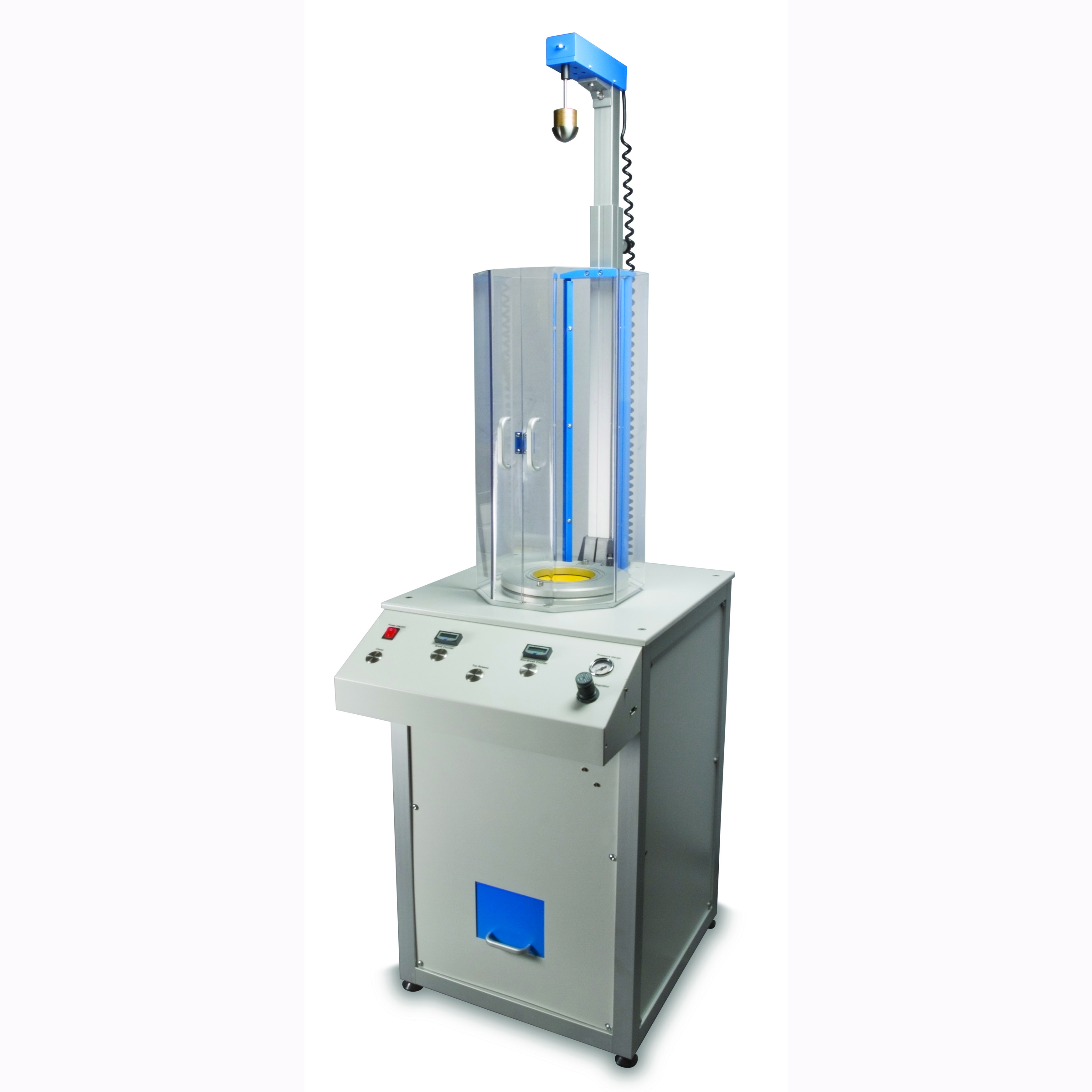
| ���Ͻ� ��ݽ�����Դϴ�. ������� �̿��� �ڵ����̹Ƿ�
����� �����ϸ�, ���Կ� ���� ������ ������ �� �־� �پ���
���� ������ �����մϴ�. |
|
|
|
Product Description
The Ray-Ran Advanced Falling Dart Impact Tester has been designed to determine the impact resistance of plastic films, papers and composite sheets by use of a free falling dart. This instrument complies with the ASTM D1709 Method A & B and ISO 7765.
The sample is clamped in position, and a dart of known weight is allowed to fall from a either 660mm or 1500mm and hit the sample. The energy required to break the samples is expressed in terms of the weight (mass) of the dart which would result in the failure of 50% of test pieces taken from the sample under test. The test methods are designed to enable the operator to achieve the result by extrapolation from the figures obtained by testing at a number of different drop weights, on a significant number of test specimens. The determination of the result is obtained using the staircase method. The dart weight is decreased or increased by uniform increments after each test, depending on the result (failure or no failure) in the specimen. |
|
|
|
Standard features include
Variable height from 660mm to 1525mm, 38.1mm and 50.8mm Spherical headed darts, Binary weight set, Manual clamping, Advanced dedicated microprocessor control, Touch membrane Alpha / Numeric keypad for data entry, LCD display for sequence logic menu auto prompt selection, Yes / no mode selector, RS232 output with data transfer lead, Specview ?Scada?software to allow PC control of Tester and real-time viewing of results, Self-calibration procedure, Results downloaded to PC for spreadsheet analysis, Metric units of measure, Ability to store User Names and Material Types, Recipe Manager to store and upload data, High resolution positional encoder, Solenoid dart release, Levelling device, Full safety guarding electrically inhibiting operation when not closed, Fully traceable certificate of calibration, Product user manual, CE mark of conformity, 1 year return to base warranty |
|
|
|
Part Numbers
RR/FD Advanced Falling Dart Impact Tester. |
|
|
|
Complies with Standard(s)
ISO 7765-1, ASTM D1709 |
|
|
|
| |
|
|
|
| |
|
|
|
| |
|
|
|
| |
 |
|
|
|
|
 |
|
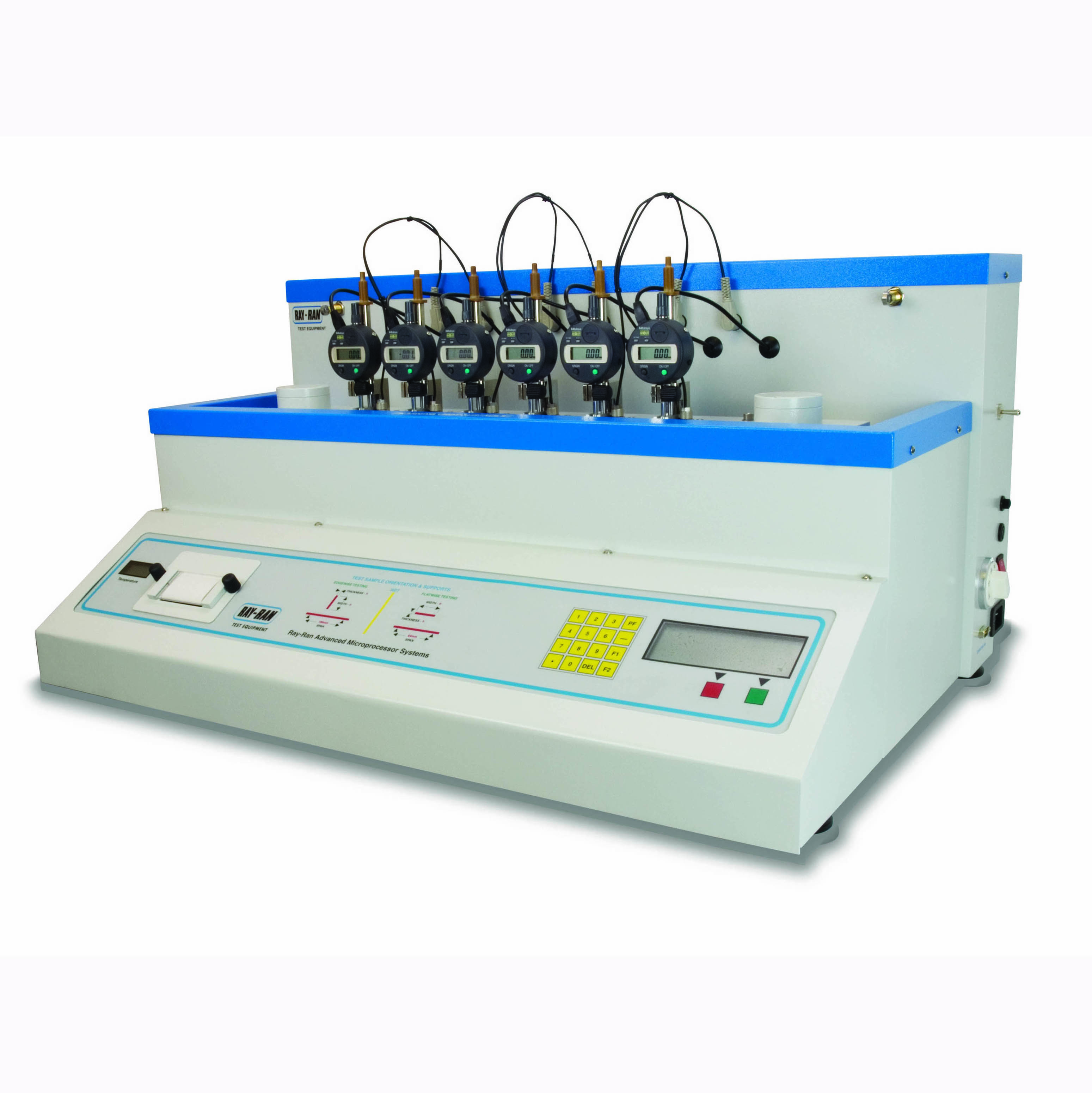
| ������-��ȭ�� ���� �����ν� ����ȭ�� ���� ������ ������
�����ϴ� ����Դϴ�. ����ũ�����μ����� ���� �ڵ�����,
�ڵ� �ð����, ��ü�������� ����� LCDȭ������ ������
���� �����մϴ�. ���� 2��, 4��, 6�� ���� �ֽ��ϴ�. |
|
|
|
Standard features include
Digital temperature control, Temperature range to 300oC (temperature tests in excess of 250oC require the nitrogen blanket option), HDT Heads (1 per station), Vicat Nibs (1 per station), User selectable Fibre Stress 0.45, 1.8 or 8.00 MPa or a non standard fibre stress can be entered, User selectable Vicat penetration of 0.1mm or 1.00mm or a non standard penetration can be added, Temperature resolution +/- 0.1oC, User selectable temperature ramp rates of 50oC or 120oC per hour (non standard ramp rates can also be entered), Adjustable HDT span supports of 64mm or 100mm, Deflection / Penetration resolution +/- 0.001mm, Bath capacity 18 litres, RS 232 connection, RS232 Cable, Windows File Capture Software, Fully traceable certificate of calibration, Product user manual, CE mark of conformity, 1 year return to base warranty, |
|
|
|
Optional accessories available
Binary HDT Test Weights (1 set required per station), 1.00Kg Vicat Test Weights (1 set required per station), 5.00Kg Vicat Test Weights (1 set required per station), Light Weight Load rods to test to .45 MPa, Heat Transfer Medium (Silicone oil Dow Corning 350cSt), Nitrogen Blanket, Air to Nitrogen Extractor,Thermal Printer (for 2 & 4 Station), Thermal Printer Paper (for 2 & 4 Station), Water Chiller unit. |
|
|
|
Test Description
HDT - Determines the temperature at which a test sample subjected to a predetermined bending stress, deflects to a set distance.
Vicat determines the temperature at which an indenter penetrates into the test sample when a given load is applied |
|
|
|
Part Numbers
RR/HDV2 2 STATION Advanced HDT/Vicat Apparatus RR/HDV4 4 STATION Advanced HDT/Vicat Apparatus RR/HDV6 6 STATION Advanced HDT/Vicat Apparatus |
|
|
|
Complies with Standard(s)
ISO 75-3, ISO 75-2, ISO 75-1, ISO 306, BS 2782: Part 1: Method 121A & B, BS 2782: Part 1: Method 120 A to E, ASTM D5945, ASTM D5944, ASTM D1525 |
|
|
|
| |
|
|
|
| |
|
|
|
| |
|
|
|
| |
 |
|
|
|
|
 |
|
| ASTM D1505 & ISO 1183 Method D �� ���� small solid materials, in various forms, Pellets, Granules, film ���� �е��� �����մϴ�. |
|
|
|
Product Description
Digital Readout Density Column. - The gradient column method accurately measures the density of small solid materials, in various forms, Pellets, Granules, film etc..and conforms to the ASTM D1505 & ISO 1183 Method D standards.
The density is formed by mixing two fluids having different densities. The resulting solution has a density which when introduced into the column increases uniformly from top to bottom.
Ray-Ran's new advancement means that density measurements can be made more quickly and more accurately.
The height of the calibrated marker floats or samples introduced into the density gradient are measured using a trammel guided "sight" connected to a positional encoder relaying the height position to a microprocessor so that the density can be obtained without the need for graphs etc.
This also means that the Gradient can be calibrated & checked at any time. |
|
|
|
Standard features include
Microprocessor System to accurately calculate the Density of the Sample. Twin conical flask pumped filling apparatus with motorised magnetic stirrer, Automatic column clearing device - sweep basket arrested automatically at top and bottom of column and pivoted for use over any of the 3 columns, Digital Temperature Controller accurate to +/- 0.1 �C, RS232 output, Built-in cooling coil, black or white twin background to assist sighting different colour samples, Microprocessor Auto Calibration System, Fully traceable certificate of calibration, Product user manual, CE mark of conformity |
|
|
|
Optional accessories available.
Microprocessor Controlled Filling System, Water chiller unit, glass marker floats, Thermal printer |
|
|
|
Test Description
When a sample material is placed in the density column its height in the column is measured using the trammel system "sight" and the microprocessor then calculates the corresponding density. |
|
|
|
|
|
Part Numbers
RR/DGA .- Auto Density Measurement System .- RR/DGA/CFS. - Computerised Filling System - RR/DGA/CU. - Water Chiller Unit - DGA/FLOAT/001. - Glass Marker Floats (density from 0.8 g/ml to 1.599 g/ml)DGA/FLOAT/002. - Glass Marker Floats (density from 1.600 g/ml to 2.200 g/ml)DGA/FLOAT/003. - Glass Marker Floats (density from 0.7 g/ml to 0.799 g/ml) |
|
|
|
Complies with Standard(s)
ISO 1183, ASTM D1505 |
|
|
|
| |
|
|
|
| |
|
|
|
| |
|
|
|
| |
|
|
|
|
|
|
|
| ������-��ȭ�� ���� �����ν� ����ȭ�� ���� ������ ������
�����ϴ� ����Դϴ�. ����ũ�����μ����� ���� �ڵ�����,
�ڵ� �ð����, ��ü�������� ����� LCDȭ������ ������
���� �����մϴ�. ���� 2��, 4��, 6�� ���� �ֽ��ϴ�. |
|
|
|
Product Description
Ray-Ran's Advanced 4 Station HDT/Vicat Apparatus has been designed to allow microprocessor control of the heat deflection & softening point testing for all polymer and plastic materials.
HDT - Heat deflection / distortion test, where a standard sized test specimen is subjected to a bending stress, whilst the temperature is raised at a uniform rate. The temperature at which the specified deflection occurs is measured and recorded. Testing is carried out in accordance with the ISO 75 (parts 1, 2 and 3) and ASTM D648 Test Standards.
Vicat (VST) - Softening point test, where a specified needle (indentor) penetrates a specifed distance into a sample with a specified load, whilst the temperature is raised at a uniform rate. The temperature at which the sample was penetrated is recorded at the Vicat Softening Temperature (VST). Testing is carried out in accordance with the ISO 306 and ASTM D1525 Test Standards.
The 4 Station Advanced HDT/Vicat apparatus allows testing of 4 samples at the same time, with an automatic cooling system, LCD display to provide automatic prompts for test procedures, calibration and results, HDT binary loads automatically calculated by microprocessor, over temperature protection, flatwise / edgewise sample testing, integrated calibration system. Tabular results presentation. |
|
|
|
Standard features include
Digital temperature control, Temperature range to 300oC (temperature tests in excess of 250oC require the nitrogen blanket option), HDT Heads (1 per station), Vicat Nibs (1 per station), User selectable Fibre Stress 0.45, 1.8 or 8.00 MPa or a non standard fibre stress can be entered, User selectable Vicat penetration of 0.1mm or 1.00mm or a non standard penetration can be added, Temperature resolution +/- 0.1oC, User selectable temperature ramp rates of 50oC or 120oC per hour (non standard ramp rates can also be entered), Adjustable HDT span supports of 64mm or 100mm, Deflection / Penetration resolution +/- 0.001mm, Bath capacity 18 litres, RS 232 connection, RS232 Cable, Windows File Capture Software, Fully traceable certificate of calibration, Product user manual, CE mark of conformity, 1 year return to base warranty, |
|
|
|
Optional accessories available
Binary HDT Test Weights (1 set required per station), 1.00Kg Vicat Test Weights (1 set required per station), 5.00Kg Vicat Test Weights (1 set required per station), Light Weight Load rods to test to .45 MPa, Heat Transfer Medium (Silicone oil Dow Corning 350cSt), Nitrogen Blanket, Air to Nitrogen Extractor,Thermal Printer (for 2 & 4 Station), Thermal Printer Paper (for 2 & 4 Station), Water Chiller unit. |
|
|
|
Test Description
HDT - Determines the temperature at which a test sample subjected to a predetermined bending stress, deflects to a set distance.
Vicat determines the temperature at which an indenter penetrates into the test sample when a given load is applied |
|
|
|
Part Numbers
RR/HDV2 2 STATION Advanced HDT/Vicat Apparatus RR/HDV4 4 STATION Advanced HDT/Vicat Apparatus RR/HDV6 6 STATION Advanced HDT/Vicat Apparatus |
|
|
|
Complies with Standard(s)
ISO 75-3, ISO 75-2, ISO 75-1, ISO 306, BS 2782: Part 1: Method 121A & B, BS 2782: Part 1: Method 120 A to E, ASTM D5945, ASTM D5944, ASTM D1525 |
|
|
|
| |
|
|
|
| |
|
|
|
| |
|
|
|
| |
 |
|
|
|
|
 |
|
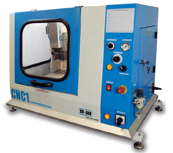
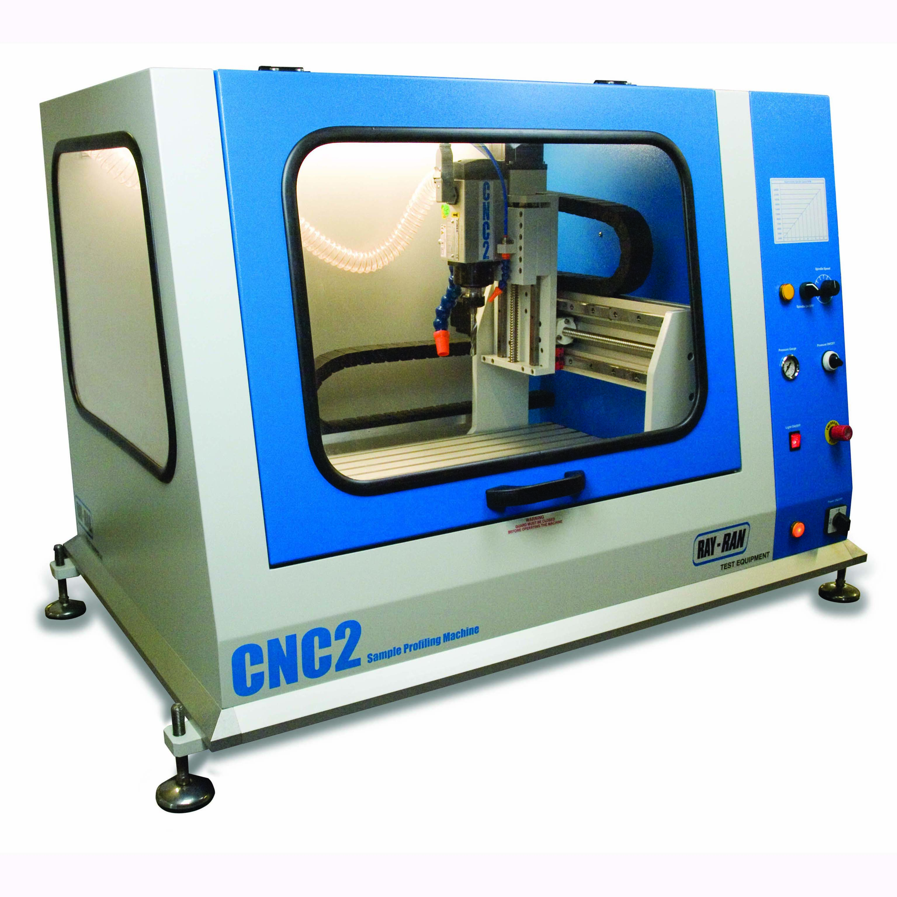
| CNC Model 1 Profile Cutter is a vertical 3 axis rapid prototyping milling machine that can be used for many application, but primarily for the cutting of test samples.
This a bench top unit measuring 67cm(W), 55cm(D), 78cm(H) |
|
|
|
Product Description
The Ray-Ran Model 1 CNC Milling Machine is a vertical 3 axis rapid prototyping machine tool that is ideal for cutting thick test samples and components. The machine is supplied as standard fully guarded with a wide up and over door which has an electrical interlock for user safety and emergency cut out switch. With USB connection the machine is connected to a personal computer or laptop, and is operated using the versatile but user friendly Windows�� Flashcut CNC PC software. The 8000- 34000rpm spindle is capable of cutting materials in 3 dimensional, simultaneous motions. Pre-written CNC programs are available direct from Ray-Ran for any shape or size of test sample to any International test standard, eliminating the need for CAD trained operators.
For the advanced user, the system has been designed to accept industry standard G & M codes ensuring full compatibility with leading professional computer aided design software. Unlimited part program size capability allows files to be run as large as your computer's hard drive will allow.
No previous CNC programming experience is required as 2 dimensional CAD drawings in *.dxf drawing file format can be imported into the Flashcut software. Once required parameters have been entered, Flashcut automatically generates the G-Code program to machine the sample.
This appartus has been designed to complement the Ray-Ran test sample injection moulding apparatus and the Ray-Ran range of test sample cutting products, For the production of test sample from sheet material up to 25mm thick |
|
|
|
Features include
300 mm x 260 mm x 80 mm XYZ axis, 500 mm x 440 mm table size, Variable spindle speeds from 8,000 rpm to 32,000 rpm, Optional Tool Changing System available, Small footprint design for desktop or bench mounting, Totally enclosed safety cabinet for user protection, Emergency Stop Button, Single line and continuous run modes with manual feed rate override, Computer interface with cabling and Windows�� Flashcut CNC PC software, Drop down menus with graphical display ��3 Dimensional graphical tool path preview, Low cost CNC programs available to any International test standard, Set of 3 Carbide milling cutters, Vice and clamps, Uses industry standard G & M codes �� Product user manual, CE declaration of conformity, 1 year return to base manufacturer's warranty. |
|
|
|
Test Description
A 3 Axis CNC Milling Machine ideal for machining test samples and small 2 dimensional components too thick for a cutting out with a press and profile cutter
Ray-Ran can provide pre-written programs. |
|
|
|
Part Numbers
RR/CNC model 1. |
|
|
|
| |
|
|
|
| |
|
|
|
| |
|
|
|
| |
 |
|
|
|
|
 |
|
| A vertical desktop CNC milling machine for rapid prototyping and production of laboratory test samples from thick sheet material or pipe sections up to 65mm thick Supplied as standard with a USB interface for a personal computer or laptop, and versatile but user friendly Windows Flashcut CNC PC Software. |
|
|
|
Product Description
Large CNC Milling Machine designed for the pipe manufacturing industry. Primarily to cut samples from thick walled pipe sections and thick sheet up to 60mm
Fully guarded with wide up-and-over door. with an
X axis of 900 mm, Y axis of 300 mm Z axis of 80 mm with a table size 500 mm by 440 mm
A range of cutter spindles available with speeds up to 23,000 rpm
Operated from a stand alone PC and Flashcut CNC PC Software |
|
|
|
Test Description
Small CNC Milling Machine to produce complex shapes, such as Dogbones & Dumbells from very thick material |
|
|
|
Part Numbers
RR/CNC2 |
|
|
|
| |
|
|
|
| |
|
|
|
| |
|
|
|
| |
 |
|
|
|
|
 |
|
| ����ڿ� ���� ������ ������� ���۵� Cutter �� �̿� ���� �ʸ��� Cutting �մϴ�. |
|
|
|
Product Description
Trammel Cutters Ideal for cutting an accurate strip of thin film material. |
|
|
|
Test Description
The point cutters are assembled in pairs and spaced apart with a setting block equal to the width of the test sample required |
|
|
|
Part Numbers
Made to Customer's requirements |
|
|
|
| |
|
|
|
| |
|
|
|
| |
|
|
|
| |
 |
|
|
|
|
 |
|
| ���¿��� �ö�ƽ ������ ��ῡ ����� �� ��������
�뼺 ������ ���˴ϴ�.
ISO 794 �� ASTM D746 �� ���� ���� ������ 50%�� �ν������� �µ��� �����մϴ�. |
|
|
|
Product Description
Designed to study the effects on plastic polymers when subject to impact loads at low temperature. Many materials which are flexible at normal ambient temperature become brittle at low temperatures, which severely affect the material�s impact strength. By plotting the percentage failure rate of the test samples against the reduction in temperature, the brittleness temperature where 50% of the test samples will fail can be determined as per the ASTM D746 and ISO R974 International Test Standard.
The Ray-Ran Low Temperature Brittleness Apparatus consists of a tank, which by using Dry Ice is bought to the starting temperature. The samples are placed into the clamping mechanism and fixed into the tank and subjected to a single blow after the specified conditioning period has elapsed. The samples are removed and examined to determine whether they have failed or not. The temperature and number of failures is then recorded. By increasing or decreasing the temperature the lowest and highest temperature at which all the samples pass and fail can be determined. |
|
|
|
Standard features include
Test specimen Cutter to produce test samples, Test specimen clamp to hold the test samples in a cantilever beam support, Test specimen striker, Insulated bath with digital temperature control and integral stirrer to ensure a uniform bath temperature, Temperature range from - 70oC to 200oC, Product user manual, CE mark of conformity, 1 year return to base warranty. |
|
|
|
Optional accessories available
Type A, B or C Cutter, Specimen Clamps to customers specifications. |
|
|
|
Test Description
To determine the Impact Resistance of polymer materials at low temperatures. The temperature is determined at which 50% of the test samples fail. |
|
|
|
Part Numbers
RR/LTB - Low Temperature Brittleness Tester |
|
|
|
Complies with Standard(s)
ISO 974, ASTM D746 |
|
|
|
| |
|
|
|
| |
|
|
|
| |
|
|
|
| |
 |
|
|
|
|
 |
|
| BS2782 : Part 1:Method 104B �� ���� ���¿��� �ö�ƽ ����� ������ ���� (Stiffness) �� �����մϴ�.
���� PVC ���� ����� ���� ���� ���迡 ���˴ϴ�. |
|
|
|
Product Description
Cold Flex Temperature Tests. Conforms to BS2782 : Part 1:Method 104B. Determines the effects of low temperatures on the stiffness of the polymer material. The appartus consists of a fixed clamp and a revolving clamp which holds the test sample rigidly at each end. The test sample is submerged in a Low Temperature Liquid Bath. The revolving clamp connects to a pulley dial indicator, graduated in 1 degrees, which is subject to a given torque produced by a dead load acting at a fixed radius. |
|
|
|
Test Description
The pulley dial inicator is locked in the zero position by a punger. The initial temperature is set so that when the plunger is released, the test sample twists about 30 deg C. The temperature is then increased by 2 deg C / min and the amount of twist measured every 5 deg C. When the angle of twist obtained is 400 degrees or greater, the resultant temperature is recorded. |
|
|
|
Part Numbers
RR/CFLEX |
|
|
|
Complies with Standard(s)
BS 2782 : PART 1: METHOD 104B |
|
|
|
| |
|
|
|
| |
|
|
|
| |
|
|
|
| |
 |
|
|
|
|
 |
|
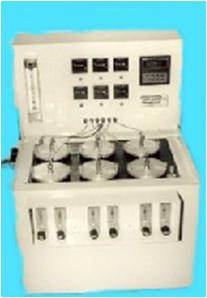
| ������ ��ǰ�� �Ҿ�־� �������� ��ȭ ������ �����մϴ�. 6���� �����Ǿ����� ���� 8���� ���� ������ ������ �ѹ��� �� 48���� ������ ���ÿ� ���谡�� : BS 903, BS 6746,
BS 5691, ASTM E95 �ݿ� ���� ������ �մϴ�. |
|
|
|
Product Description
This apparatus has been designed to study the thermal endurance characteristics of materials. The Ray-Ran 6 Cell Thermal Ageing apparatus accelerates the ageing process by passing a constant flow of heated air over the samples. At set time intervals the test samples are removed and inspected, or tested for any deterioration. The apparatus consists of 6 individual test cells with up to 8 samples per cell, thus allowing 48 simultaneous tests to be undertaken. |
|
|
|
Standard features include
Individual test cells, each with its own elapsed timer, Holders for dumbbell tensile samples, Constant temperature controlled liquid bath with digital temperature display, Tank capacity 30 litres, Variable volume changes between 50 -500 cm3 per hour, 6 way switchable temperature indicator to monitor the temperature in each test cell, A calibrated glass flow meter with a flexible inlet pipe can be connected, Fully traceable certificate of calibration, Product user manual, CE mark of conformity, 1 year return to base warranty. |
|
|
|
Test Description
The test samples are suspended in a precisely controlled environment with temperature controlled air continually being circulated through each Test Cell at a constant flow. The Test Samples are checked for Thermal Aging at set Time Intervals and the condition recorded. |
|
|
|
Part Numbers
RR/TAA 6 Cell Thermal Ageing Apparatus. |
|
|
|
Complies with Standard(s)
BS 903, BS 6746, BS 5691, ASTM E95 |
|
|
|
| |
|
|
|
| |
|
|
|
| |
|
|
|
| |
 |
|
|
|
|
 |
|
| ASTM D1698 �� ���� ���� ������ Notch �Ͽ� ��ǥ ��Ʈ������ ������ ���� ������ ��U������ ������ ���� ���� ���� �������� ������ �ð� �������� Notch�� ������ Crack ������ Check �մϴ�. |
|
|
|
Product Description
Environmental Stress Cracking. is one of the most common causes of unexpected brittle failure of thermoplastics polymers known. Research has shown that the exposure of polymers to liquid chemicals accelerate the crazing process.
The Ray-Ran Stress Cracking Apparatus has been designed in accordance with the ASTM D1693 test method, it is simple to use and an extremely cost effective method of determining a polymer material's susceptibility to stress cracking when exposed to different environments such as soaps, wetting agents, oils and detergents.
The material is cut to shape with the die cutter provided and notched and then the test sample bent into a "U" section to induce the required stress. The samples are placed into the sample holders which are then transferred to the glass test tubes. These tubes are filled with the selected environment and heated. At timed intervals the samples are checked for any cracks developing adjacent to the notch. The number of failures is recorded. |
|
|
|
Standard features include
Digital temperature display and control, Constant temperature controlled stainless steel liquid bath, Sample Cutter to cut out test samples, Sample nicking jig to make the controlled imperfection in the test samples, Sample bending clamp to bend the test samples into a controlled "U" shape, Specimen holders to house the test samples in the test tubes (up to 10 test samples can be housed in each specimen holder), Sample transfer tool to move the test sample from the clamp to the specimen holders, 48 glass test tubes and rubber stoppers, Product user manual, CE mark of conformity, 1 year return to base warranty,
|
|
|
|
Test Description
The test sample is notched and then bent into a "U" section to induce the required stress. The samples are placed in the glass tubes, filled with the selected environment and heated. At regular intervals the sample are checked for any cracks developing adjacent to the notch. |
|
|
|
Part Numbers
RR/ESC - Environmental Stress Cracking Apparatus, --- ESC 029 - Spare Pack of 10 Nicking Blades |
|
|
|
Complies with Standard(s)
ASTM D1693 |
|
|
|
| |
|
|
|
| |
|
|
|
| |
|
|
|
| |
 |
|
|
|
|
 |
|
| ������ ġ���� �ʸ� ������ ������ �µ��� ������ Cover plate �� ���� �����ð��� ������� ������ ���� ������ �����մϴ�. |
|
|
|
Product Description
Although the Hot Plate Film Shrinkage Apparatus is not controlled by any International test standards, it is still a very widely used apparatus, providing information sufficient for most quality control procedures. Where precise results are essential, the Ray-Ran Unrestrained Linear Thermal Film Shrinkage Apparatus should be used. The principal of both the hot plate and the immersion methods are the same, notably to determine the amount of shrinkage of a film when heated to release the internal stresses produced due to the manufacturing methods. The hot plate method is very simple and quick to understand. A film sample of round or rectangular shape is placed on a hot plate maintained at a constant temperature, and with its surface lightly oiled with Silicone oil to ensure good heat transfer from the hot plate to the film. A light cover plate which keeps the film flat is placed on the top of the film sample. After a set time the film is re-measured and its percentage shrinkage determined. |
|
|
|
Standard features include
Digital temperature display and control, Test sample template, Test sample cover lid, Small bottle of Silicone oil, Product user manual, CE mark of conformity, 1 year return to base warranty |
|
|
|
Optional Accessories include
50mm dia Test Sample Cutter, Hand operated Cutting Press. |
|
|
|
Test Description
A Test Sample of the material is cut and its orientation with respect to the manufacturing process marked. It is then lightly coated with Silicone Oil and placed on the Hot Plate for the required time, after which its measured and the shrinkage determined. |
|
|
|
Part Numbers
RR/FSHP - Hot Plate Shrinkage Apparatus. FSHP 013 - 50mm Diameter Cutter. |
|
|
|
Complies with Standard(s)
ASTM D2732 |
|
|
|
| |
|
|
|
| |
|
|
|
| |
|
|
|
| |
 |
|
|
|
|
 |
|
| ASTM D2732 �� ���Ͽ� Plastic film & Sheet ������ ������ ��ü �ӿ� ��� ���¿����� ������ ���༺�� �����մϴ�. |
|
|
|
Product Description
Although the Hot Plate Film Shrinkage Apparatus is not controlled by any International test standards, it is still a very widely used apparatus, providing information sufficient for most quality control procedures. Where precise results are essential, the Ray-Ran Unrestrained Linear Thermal Film Shrinkage Apparatus should be used. The principal of both the hot plate and the immersion methods are the same, notably to determine the amount of shrinkage of a film when heated to release the internal stresses produced due to the manufacturing methods. The hot plate method is very simple and quick to understand. A film sample of round or rectangular shape is placed on a hot plate maintained at a constant temperature, and with its surface lightly oiled with Silicone oil to ensure good heat transfer from the hot plate to the film. A light cover plate which keeps the film flat is placed on the top of the film sample. After a set time the film is re-measured and its percentage shrinkage determined. |
|
|
|
Standard features include
Digital temperature display and control, Test sample template, Test sample cover lid, Small bottle of Silicone oil, Product user manual, CE mark of conformity, 1 year return to base warranty |
|
|
|
Optional Accessories include
50mm dia Test Sample Cutter, Hand operated Cutting Press. |
|
|
|
Test Description
A Test Sample of the material is cut and its orientation with respect to the manufacturing process marked. It is then lightly coated with Silicone Oil and placed on the Hot Plate for the required time, after which its measured and the shrinkage determined. |
|
|
|
Part Numbers
RR/FSHP - Hot Plate Shrinkage Apparatus. FSHP 013 - 50mm Diameter Cutter. |
|
|
|
Complies with Standard(s)
ASTM D2732 |
|
|
|
| |
|
|
|
| |
|
|
|
| |
|
|
|
| |
 |
|
|
|
|
 |
|
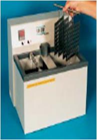
| ����ǿ��� �� ������ ���� �õ���ν� �� ����
�ִ� -60�� ���� �õ��� �����մϴ�. |
|
|
|
| |
|
|
|
| |
|
|
|
| |
|
|
|
|
|


|